Supported RAID types and parameters
RAID stands for "redundant array of independent disks" or "redundant array of inexpensive disks". It is a technology of data storage that combines two or more physical disk drives into one or more logical units (arrays). This approach improves data storage reliability, performance, or both.
The data can be distributed across physical drives of a RAID array using different standardized methods, which are called RAID types or RAID levels.
Atola TaskForce can reassemble and image the following RAID types:
This article covers currently supported RAID types and their parameters in more detail.
RAID types comparison
| RAID type and method |
Scheme of data distribution |
Description |
Common usage |
Performance |
Fault tolerance |
Capacity |
Minimum number of disks |
|
JBOD:
Spanning
|
|
Multiple physical drives are spanned, or concatenated, together to form a single logical disk with no redundancy.
|
Increasing capacity. Cost-effective storage with no performance or security benefits.
|
No benefits. Array performance equals the performance of each drive depending on data location.
|
Very low. Redundancy is not provided. If one drive fails, a failure is typically isolated to this drive.
|
Array capacity is the sum of the capacities of its members.
|
2 |
|
RAID 0:
Striping
|
|
Data is split ('striped') evenly across the drives forming a logical array, without parity or mirroring.
|
Improving reading and writing speed.
|
The highest read and write speed because data is striped across all disks, and the controller can read and write several drives in parallel with no delay due to parity calculation.
|
Very low. If one drive fails, data is lost.
|
Volume is the sum of the capacities of the drives in the set. No overhead is provided by parity blocks.
|
2 |
|
RAID 1:
Mirroring
|
|
Mirroring without parity or striping. Data is written identically to two or more drives, producing a "mirrored set" of drives.
|
Standart app servers; applications that require higher fault tolerance, than storage capacity or performance.
|
High read speed: the controller can read several drives in parallel. Lower compared to RAID 0 write speed: all data must be written to two disks.
|
High. If one drive fails, data is restored from the “mirror” drive(s).
|
Storage capacity is reduced by 1/2 as all data is written twice.
|
2 |
|
RAID 10 (1+0):
Striping and mirroring
|
|
Striped set from a series of mirrored drives. Data is shared between disks and duplicated.
|
Highly utilized database, email, web servers.
|
High read speed similar to RAID 1 due to improved read rates through simultaneous disk reads.Moderate to high write speed because data is mirrored across pairs, but the striping allows for higher write speeds compared to just RAID 1.
|
Very high fault tolerance. The array can sustain multiple drive losses so long as no mirror loses all its drives.
|
Storage capacity is reduced by 1/2 as all data is written twice.
|
4 |
|
RAID 5:
Striping and parity
|
|
Data is split ('striped') evenly across the drives with added distributed parity.
|
Normal file storage and app servers.
|
High read speed but slightly lower than RAID 0 because of the overhead from parity calculations and distribution across all disks. Moderate write speed due to the need for parity calculations and writing both data and parity information.
|
High. If one drive fails, data can still be calculated from the distributed parity.
|
Due to parity blocks, storage capacity equals the smallest drive capacity multiplied by (N−1) drives.
|
3 |
|
RAID 6:
Striping and double parity
|
|
Data is split ('striped') evenly across the drives with two distributed parity blocks, instead of one.
|
Large file storage and app servers.
|
High read speed similar to RAID 5, but can be slightly slower due to additional parity calculations. Write speed is lower than RAID 5 because it requires two parity blocks to be written.
|
Very high fault tolerance due to double parity. Data can still be calculated even if two drives fail.
|
Due to dual parity blocks, storage capacity equals the smallest drive capacity multiplied by (N−2) drives.
|
4 |
RAID parameters
Each individual RAID is defined by a combination of several main parameters:
To identify RAID type and exact parameters, TaskForce automatically checks up to 200,000,000 RAID parameter combinations. However, if you know the exact RAID configuration, you can enter it manually.
Depending on the RAID type, different sets of parameters can be applied:
| Parameter |
JBOD |
RAID 0 |
RAID 1 |
RAID 10 |
RAID 5 |
RAID 6 |
| Number of devices |
|
|
|
|
+ missing |
+ missing |
| Device order |
|
|
|
|
|
|
| Start LBA |
|
|
|
|
|
|
Block size |
− |
|
− |
|
|
|
| RAID 1 groups |
− |
− |
− |
|
− |
− |
| Block order |
− |
− |
− |
− |
|
|
| Parity block order/type |
− |
− |
− |
− |
− |
|
Here’s what each of the RAID parameters means.
RAID type (or RAID level)
RAID type is defined by the method in which data is distributed across physical drives combining the array. TaskForce currently supports the following RAID types:
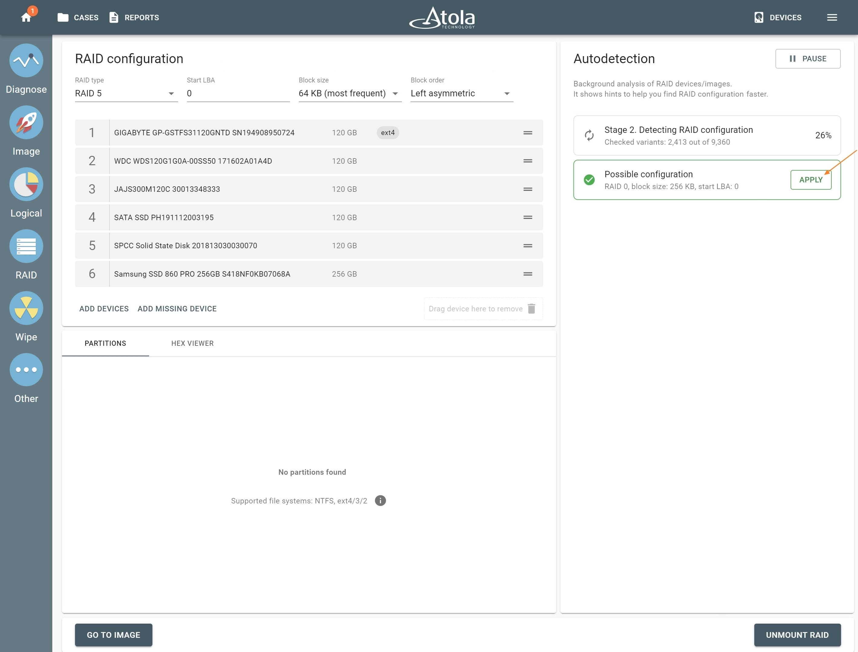
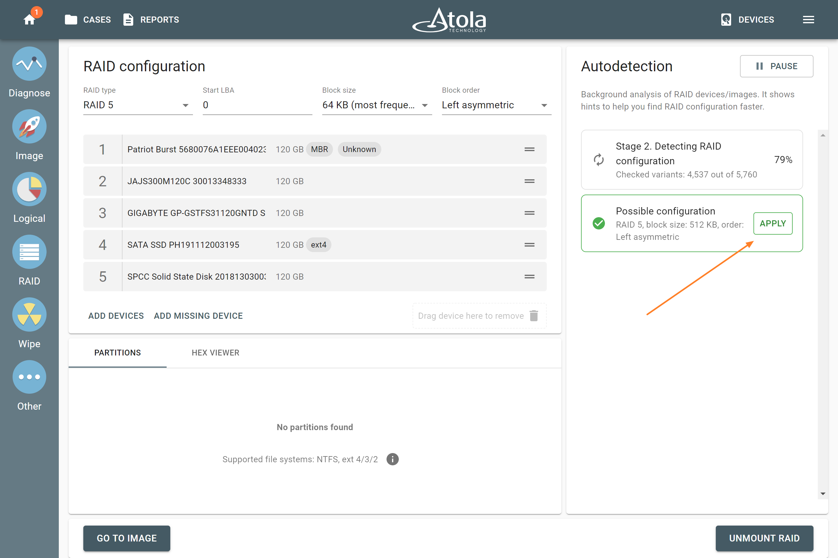
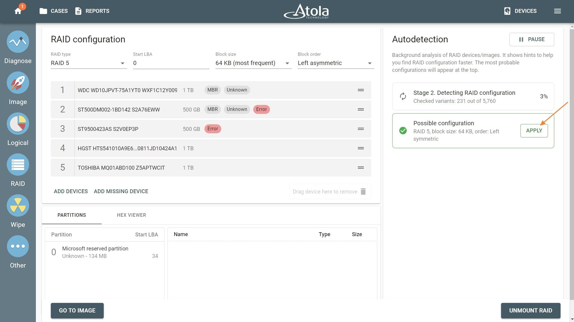
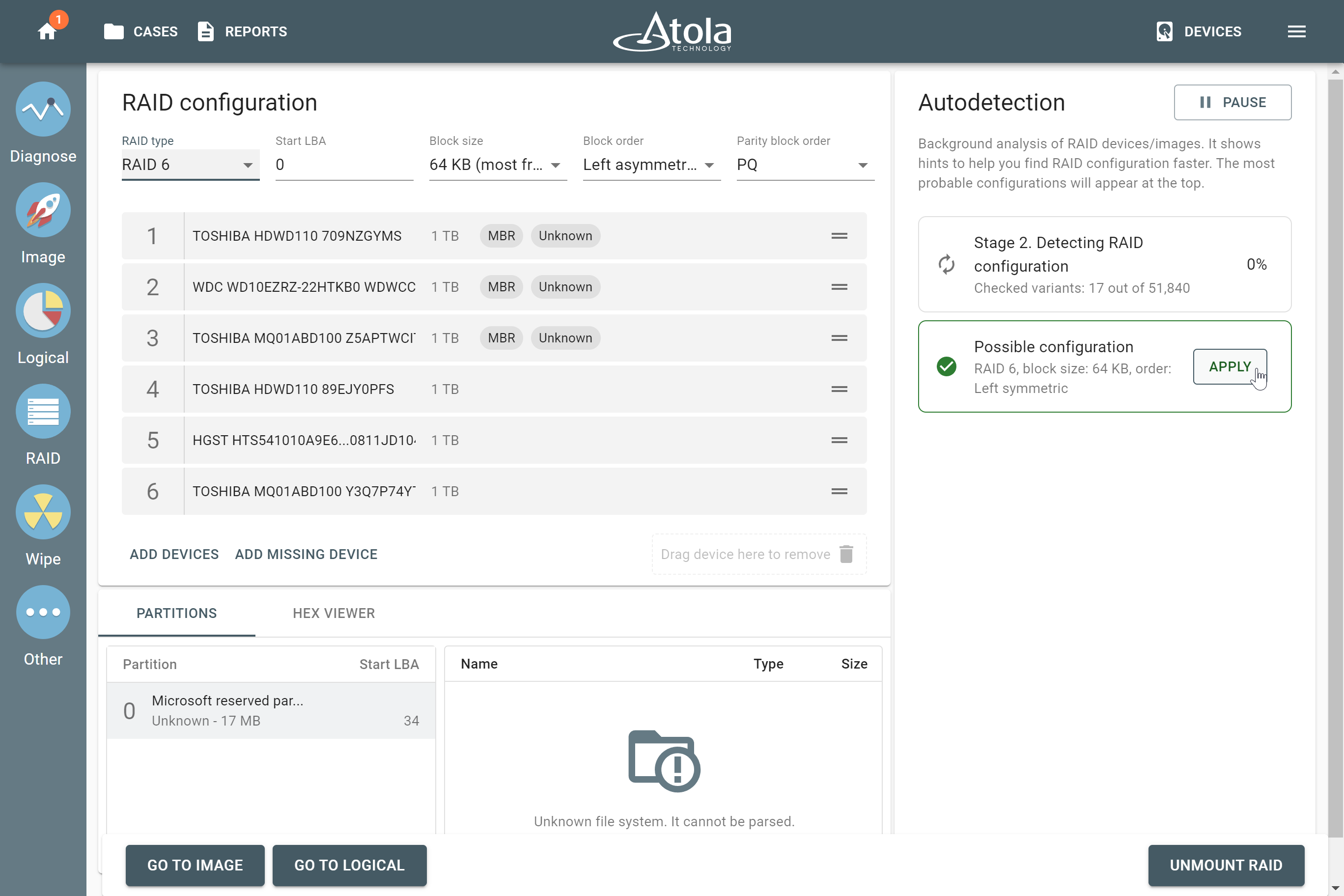
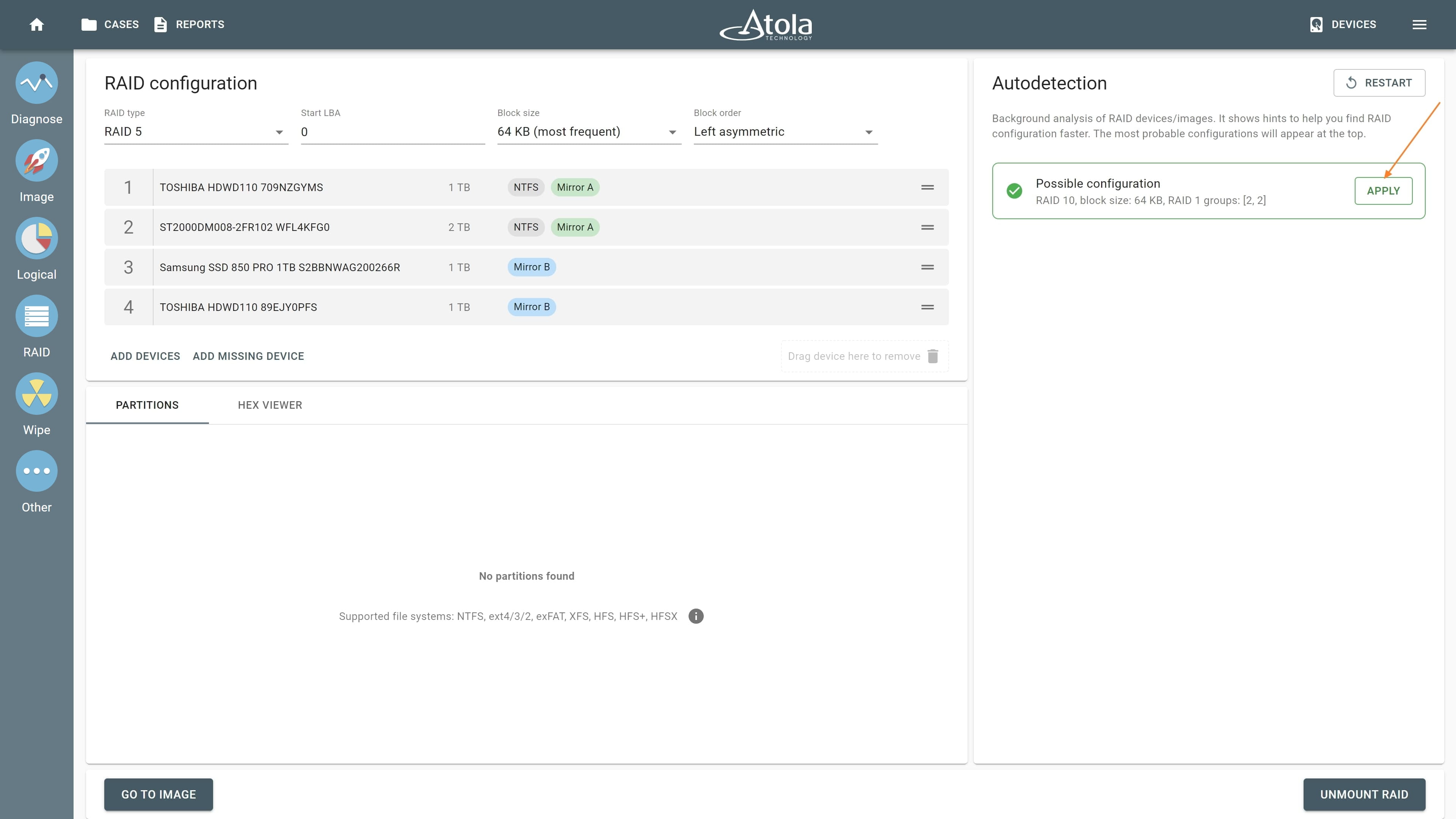
In TaskForce, the RAID type can be automatically identified by the Autodetection module along with other parameters.
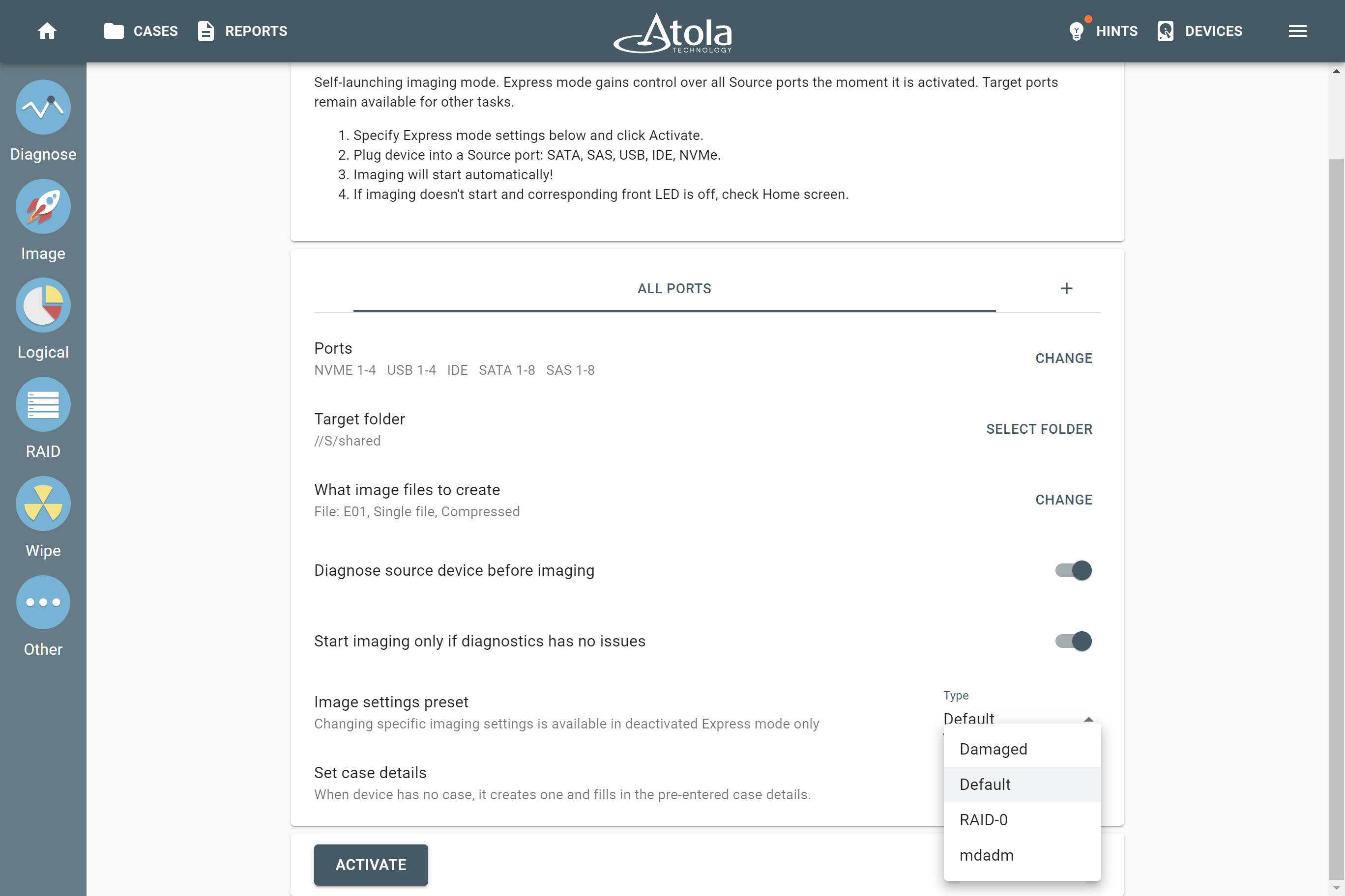
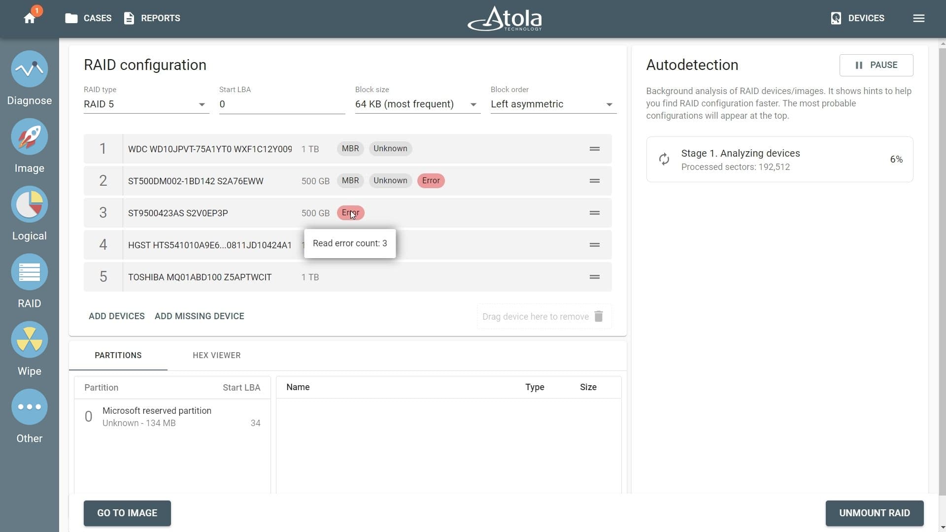
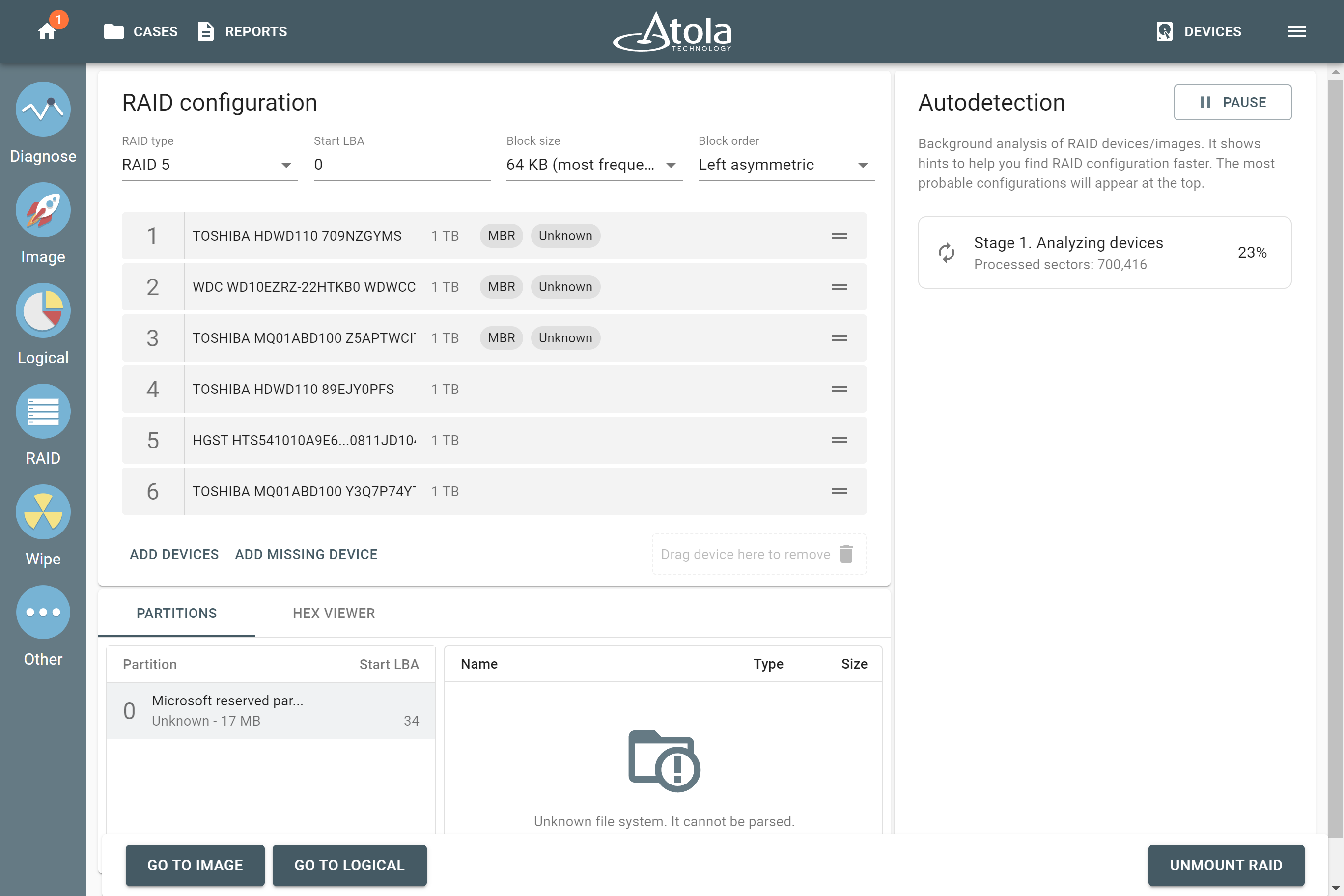
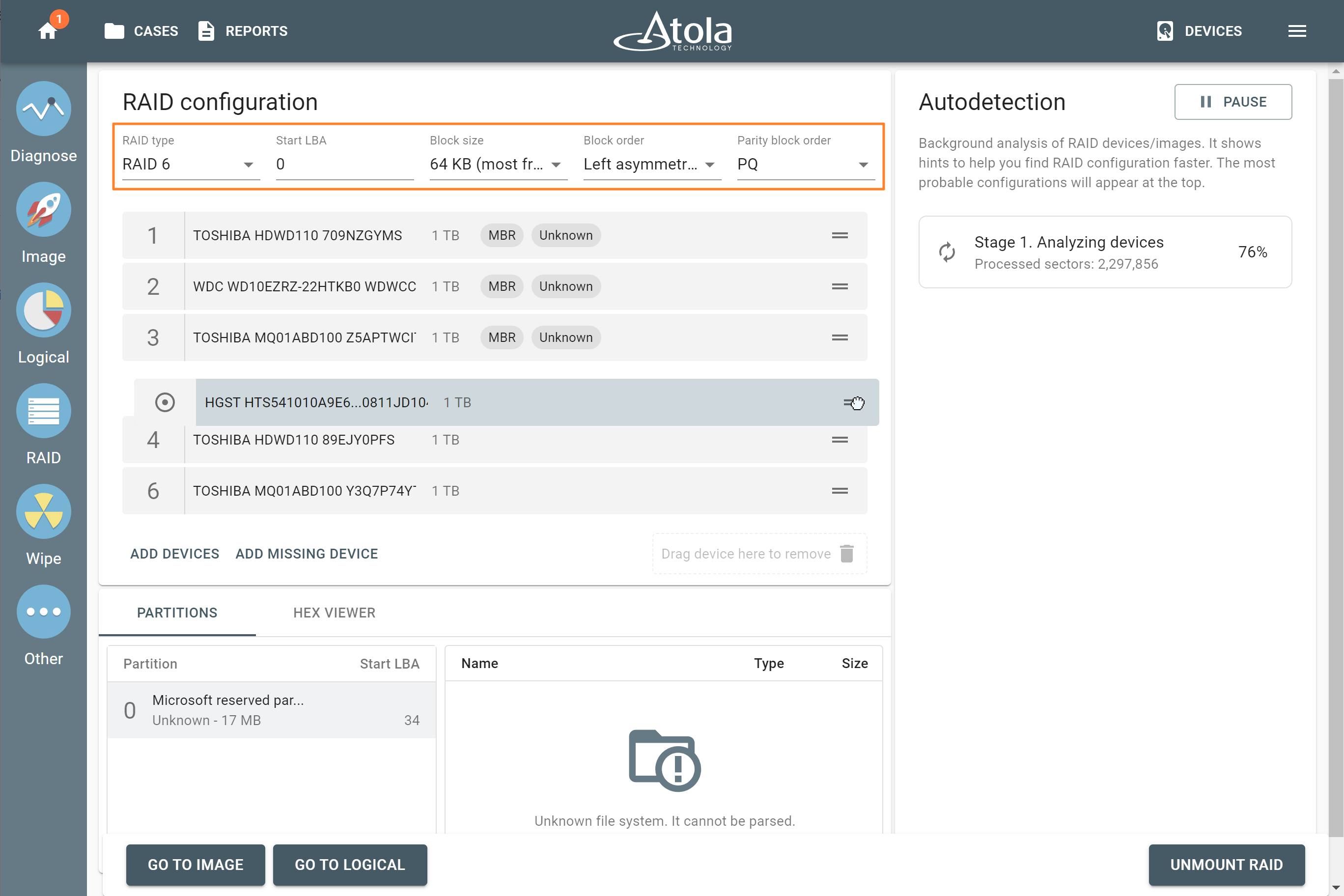
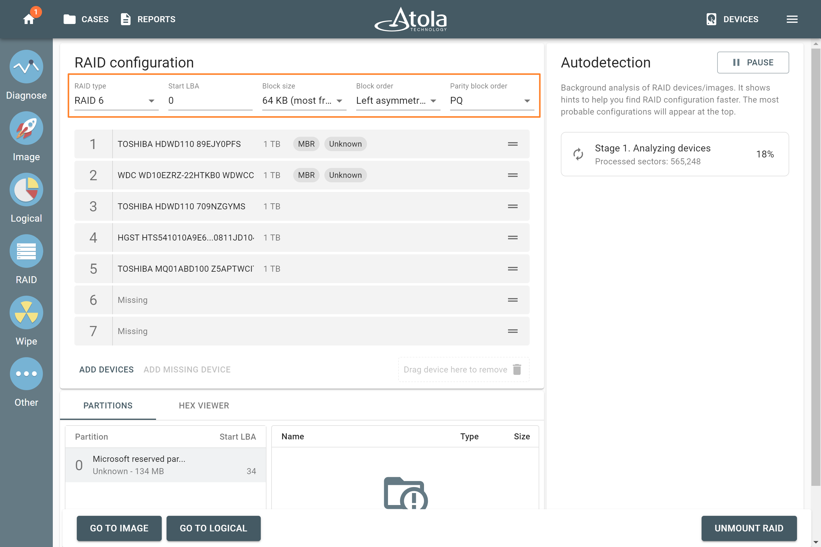
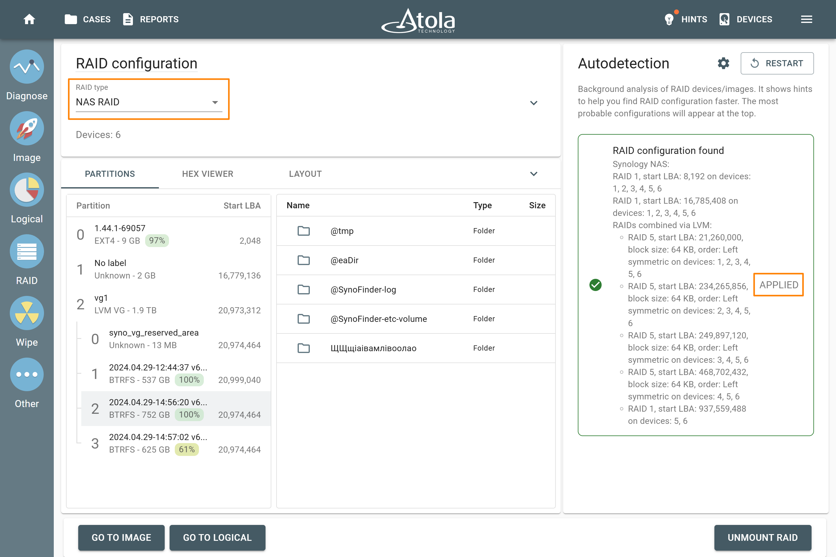
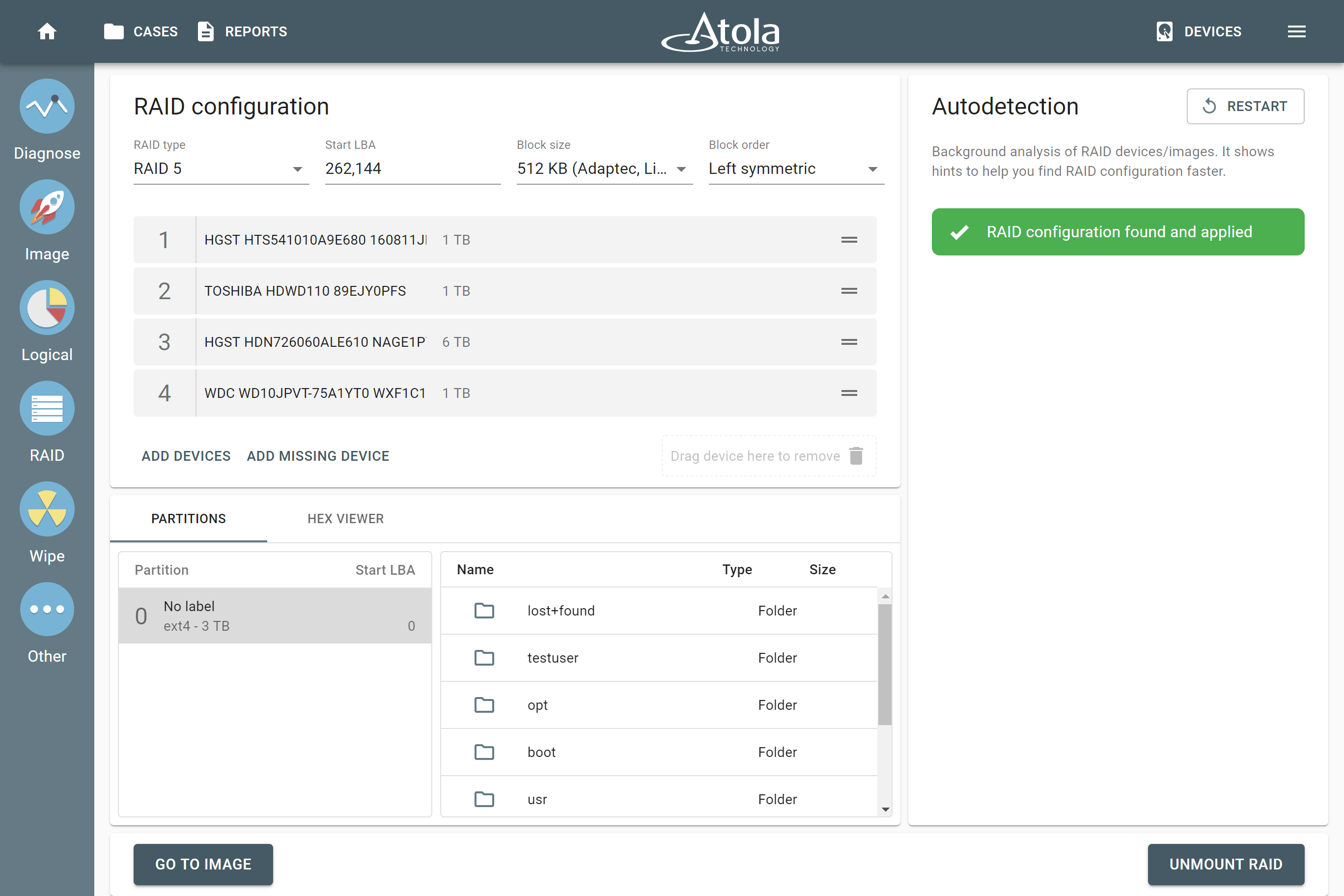
However, if you know the RAID type, you can select it manually from the RAID type list in the RAID configuration section.

The RAID type list in the RAID configuration section.
Number of devices
Applies to: all supported RAID types.
The minimum number of disks needed to build a RAID array is:
- two for JBOD, RAID 0, and RAID 1,
- three for RAID 5,
- four for RAID 10 and RAID 6.
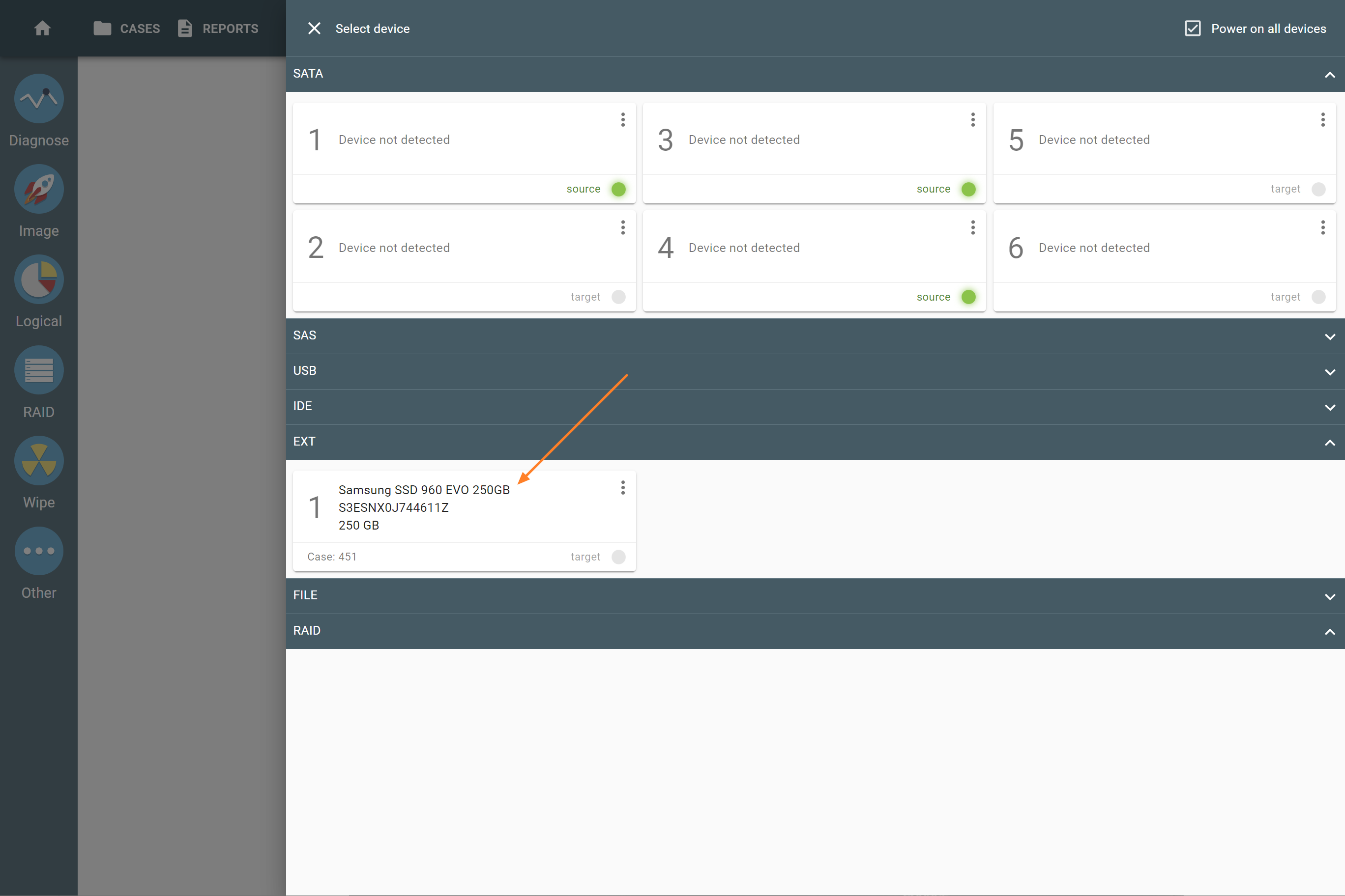
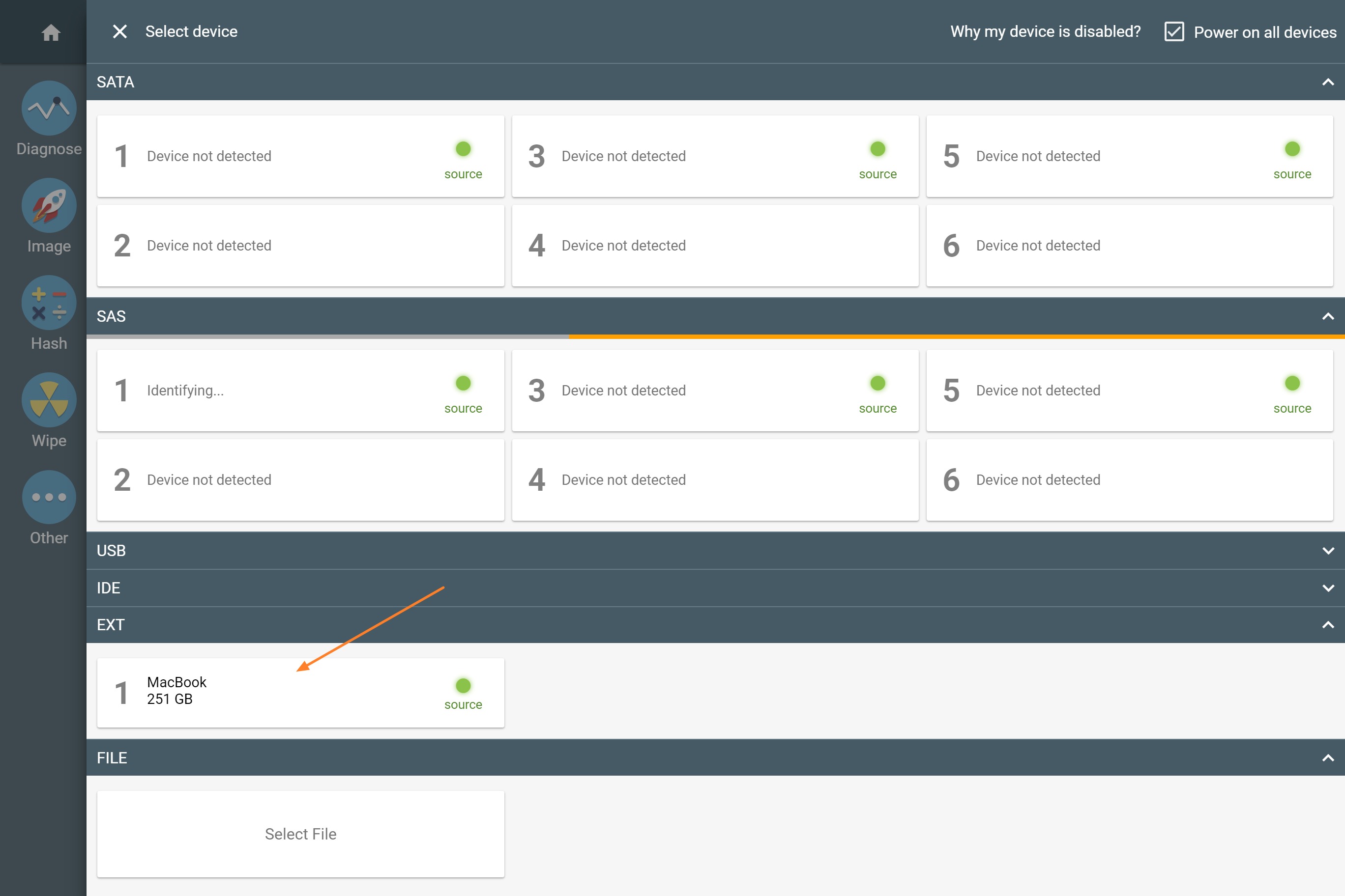
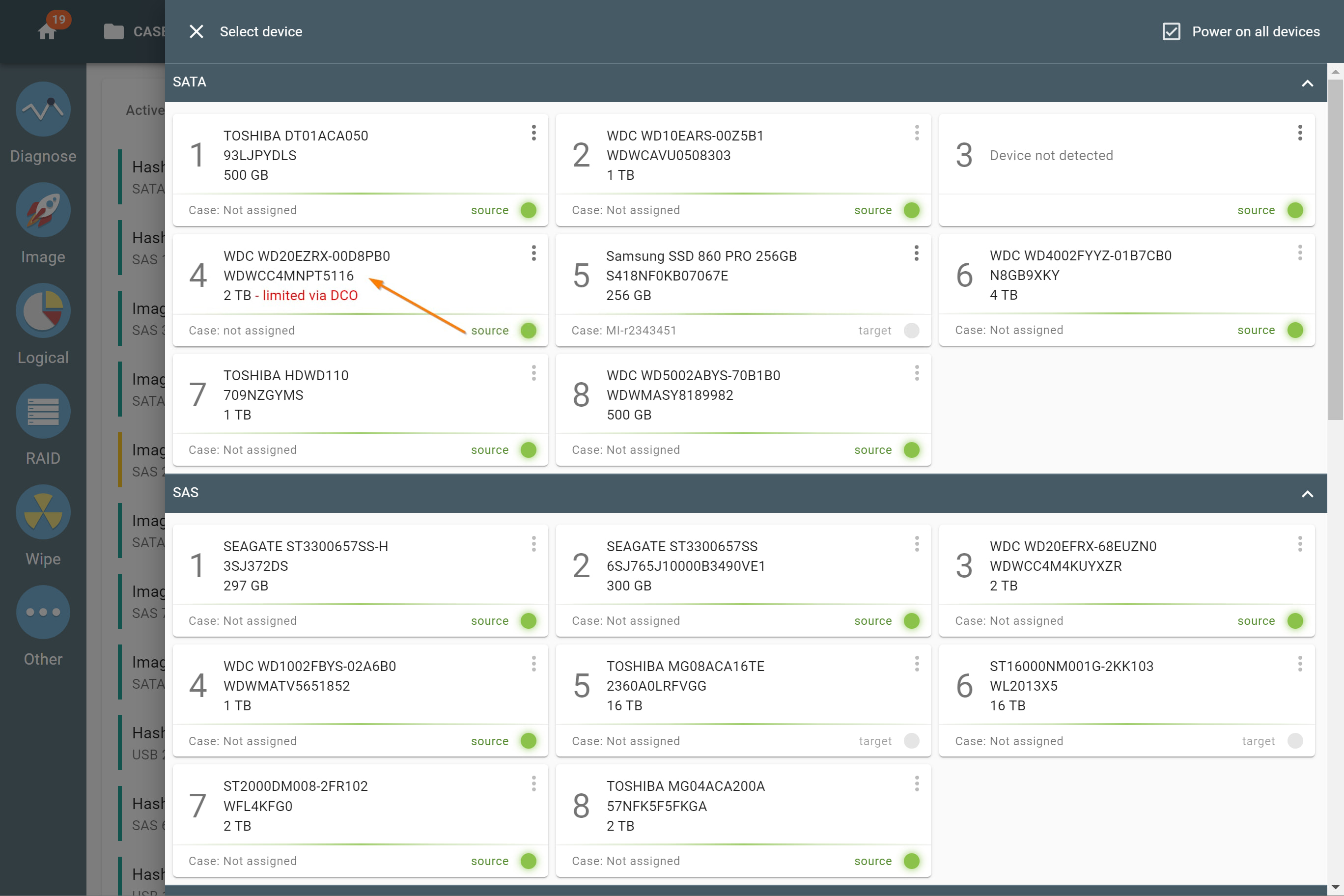
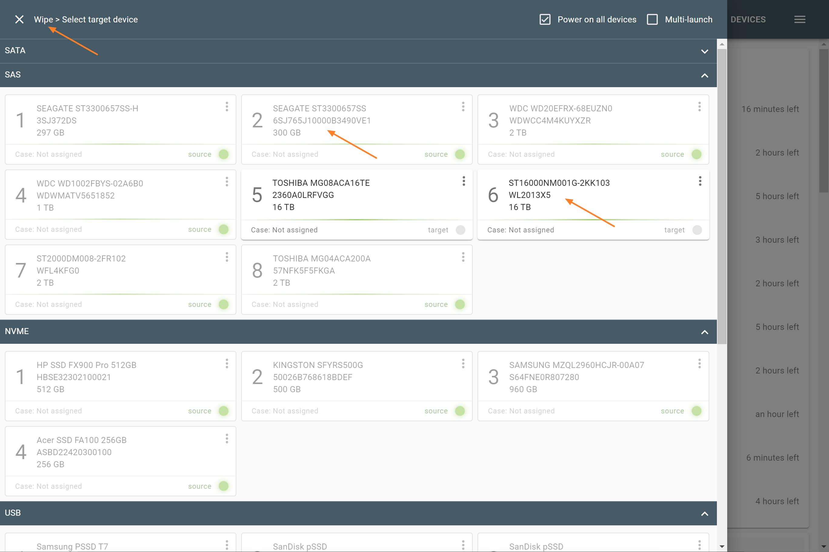
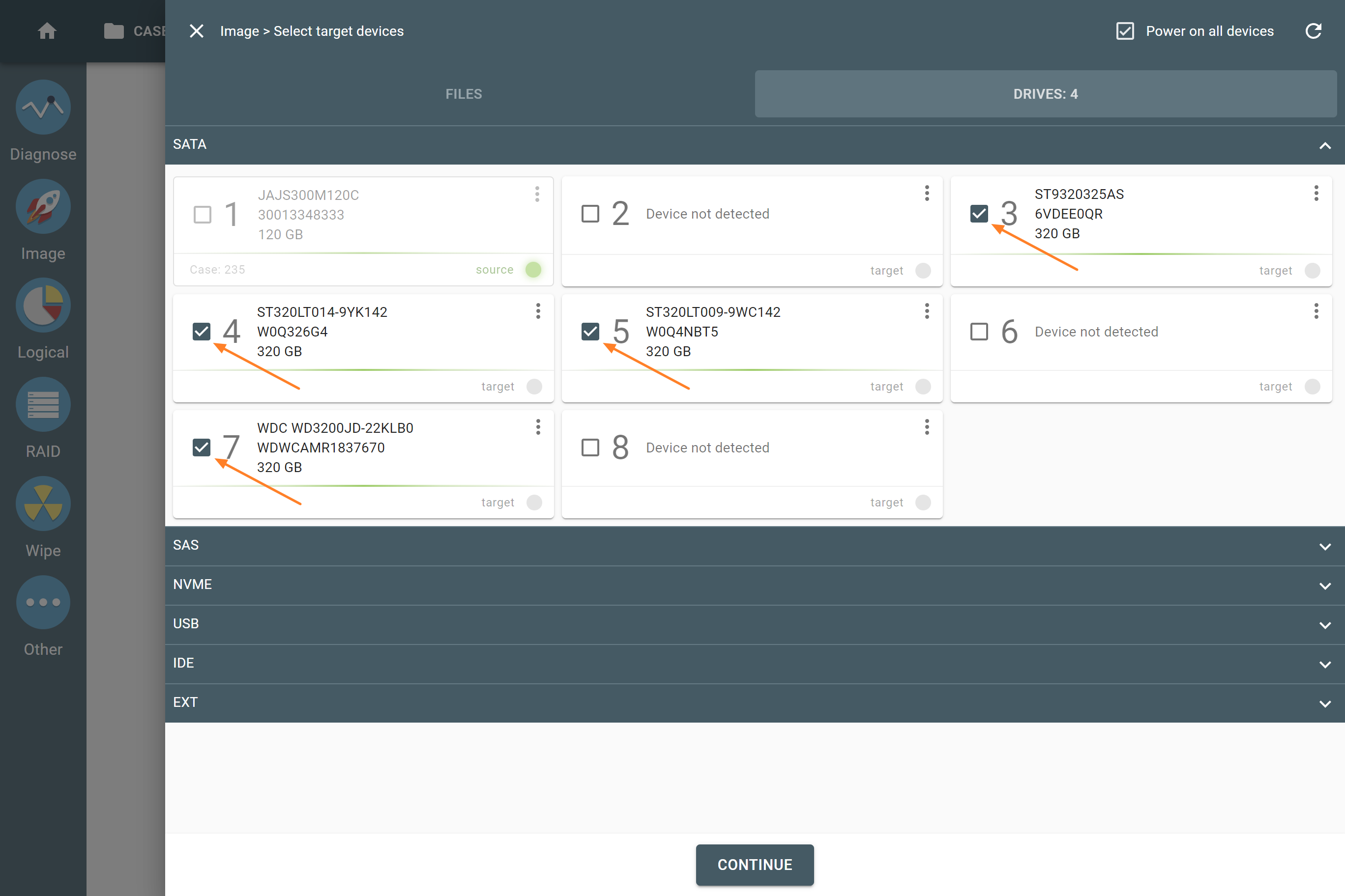
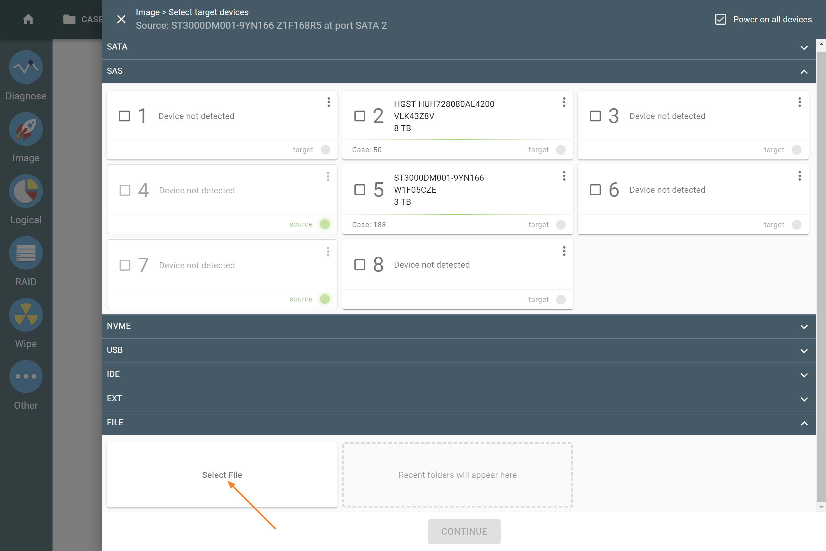
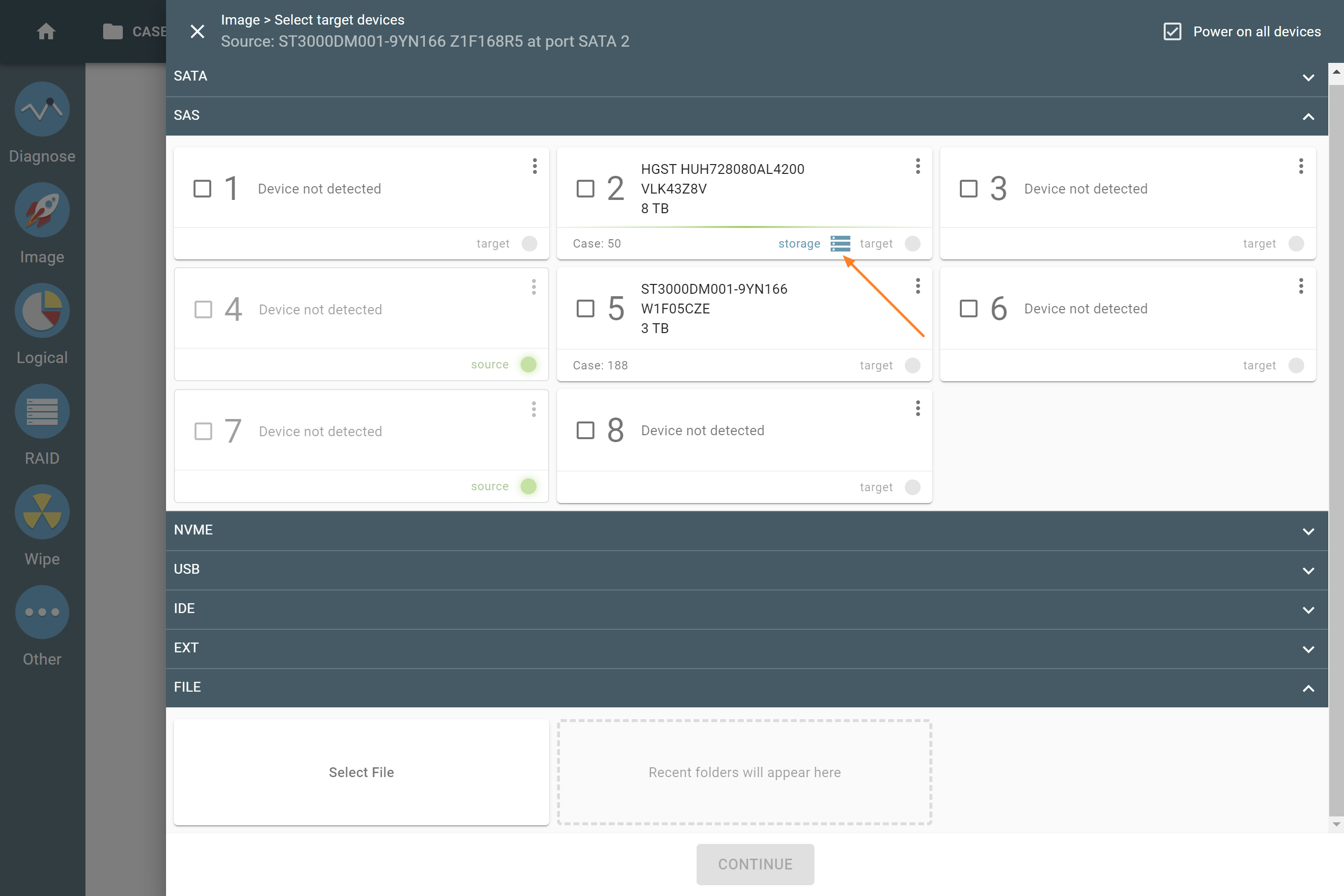
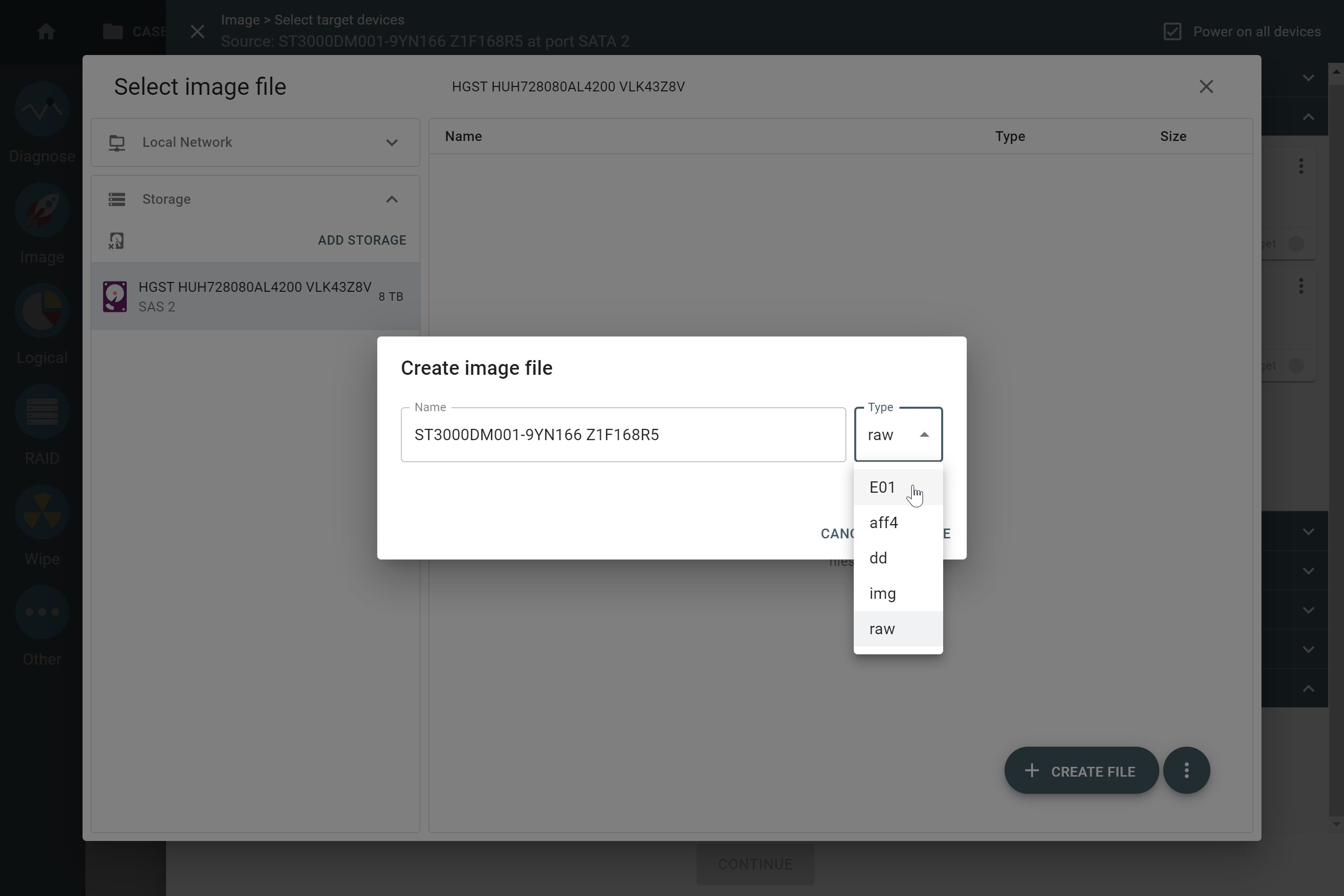
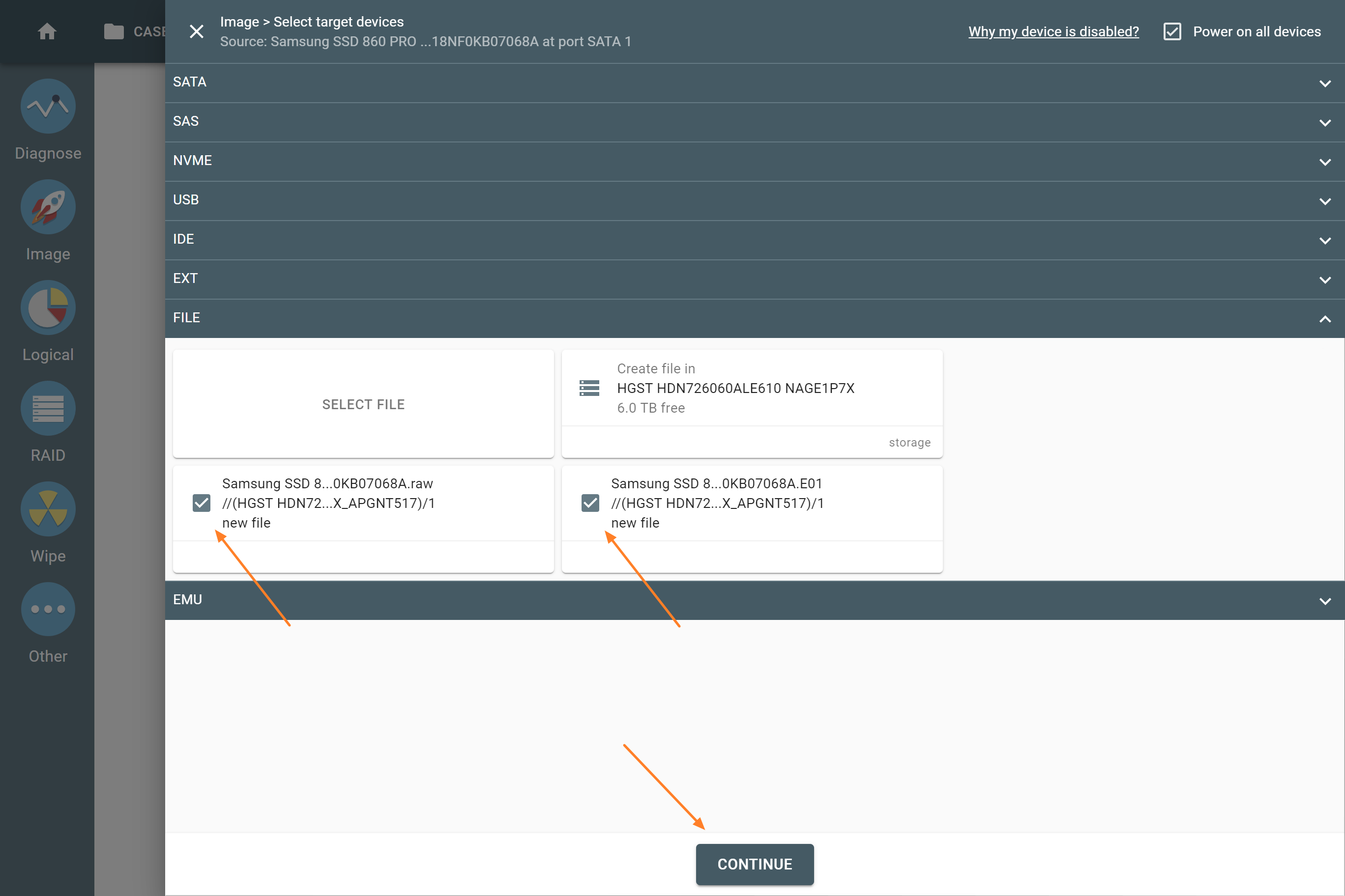
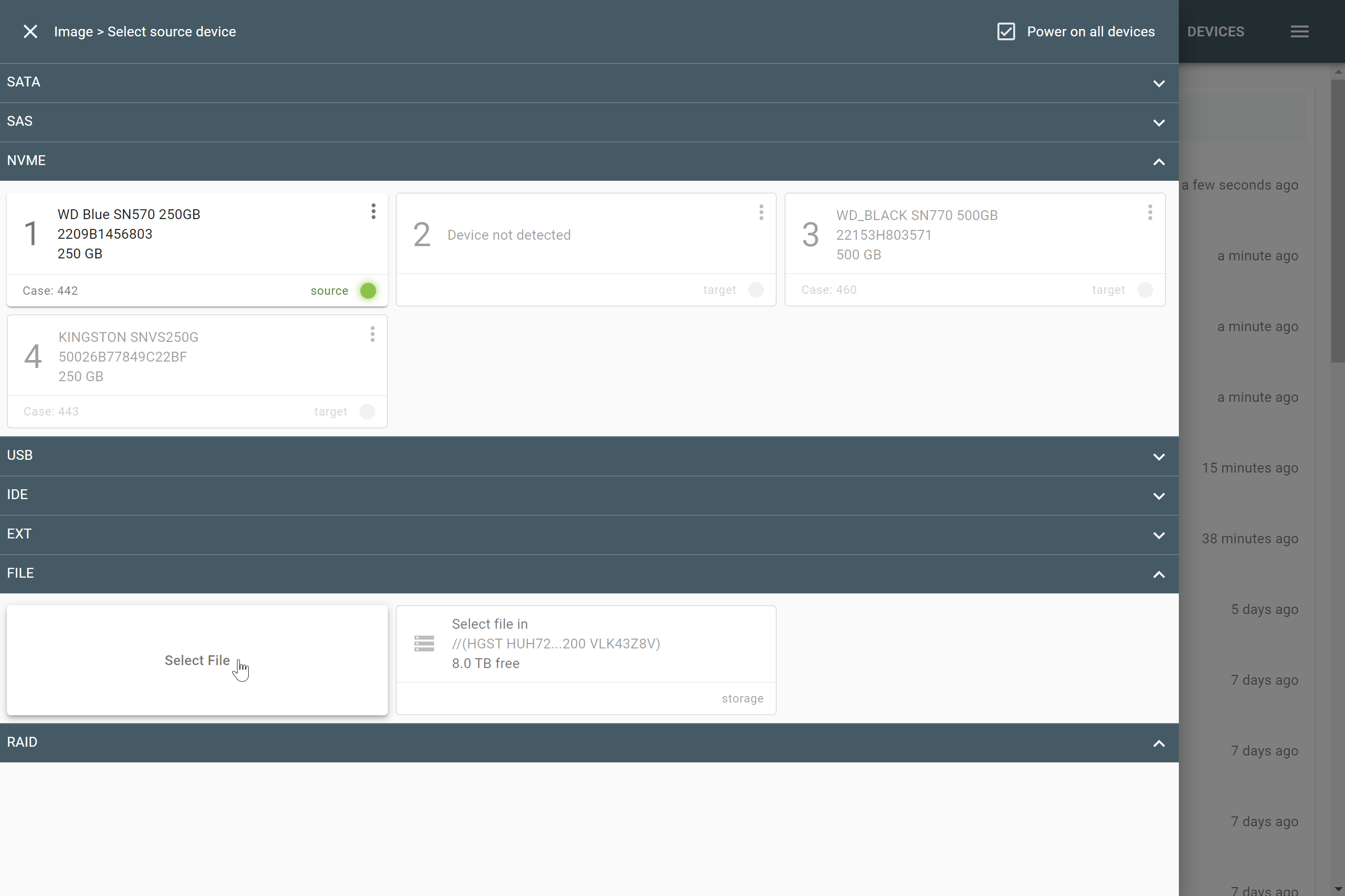
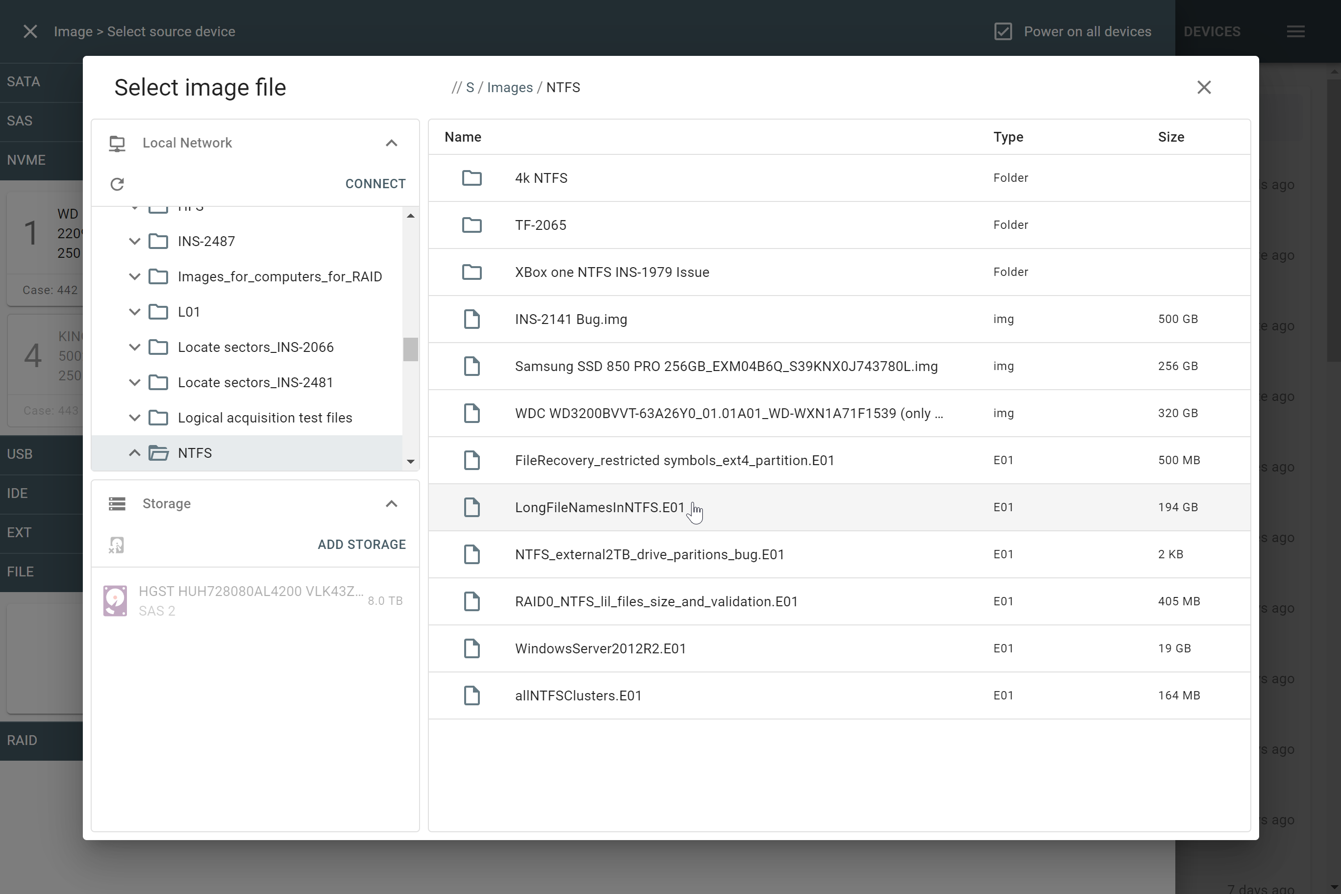
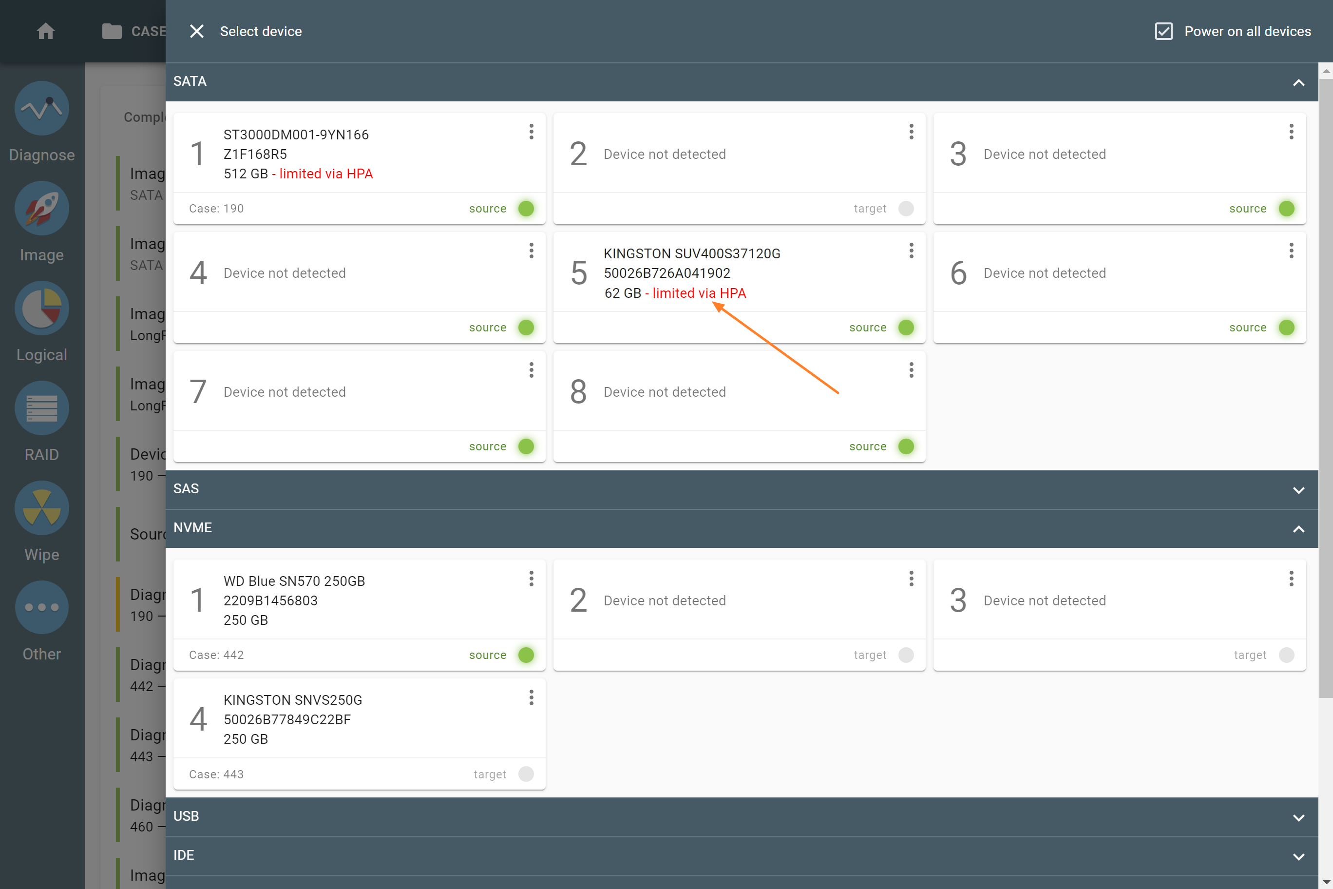
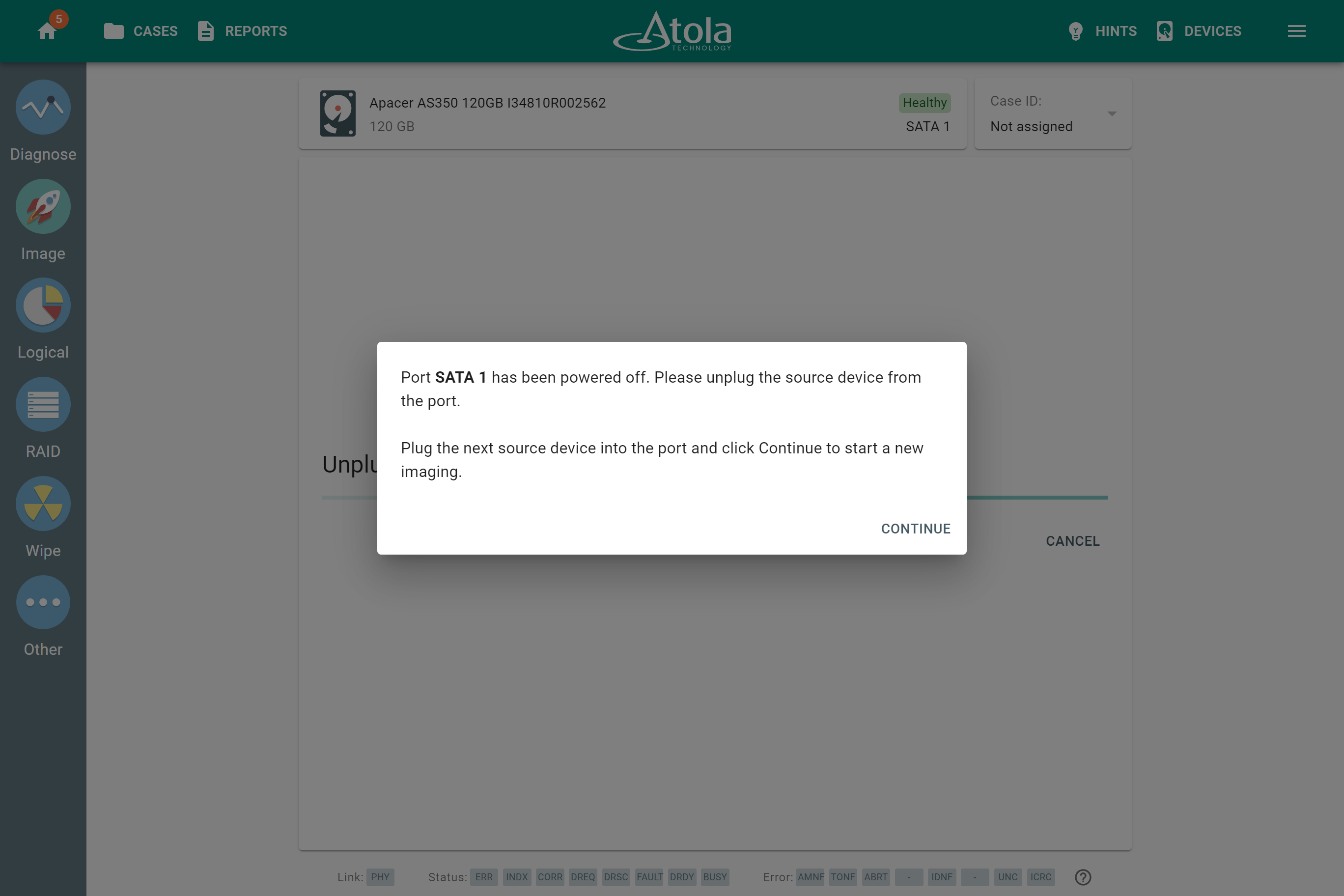
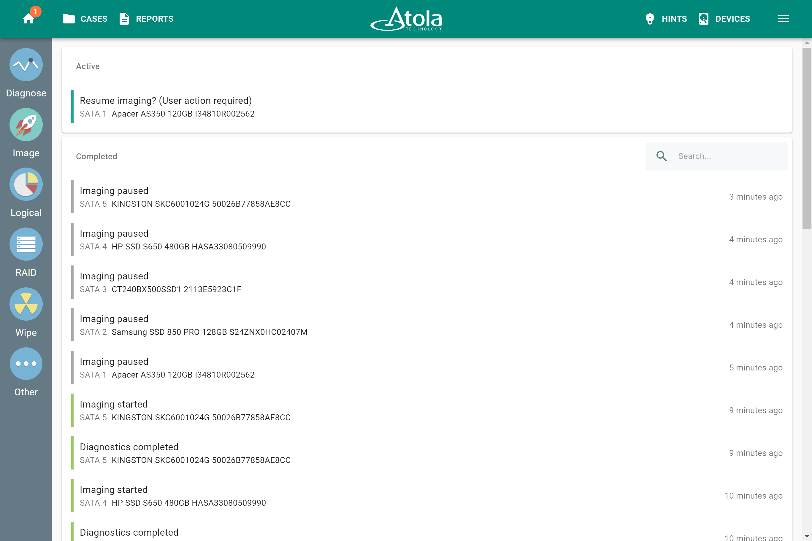
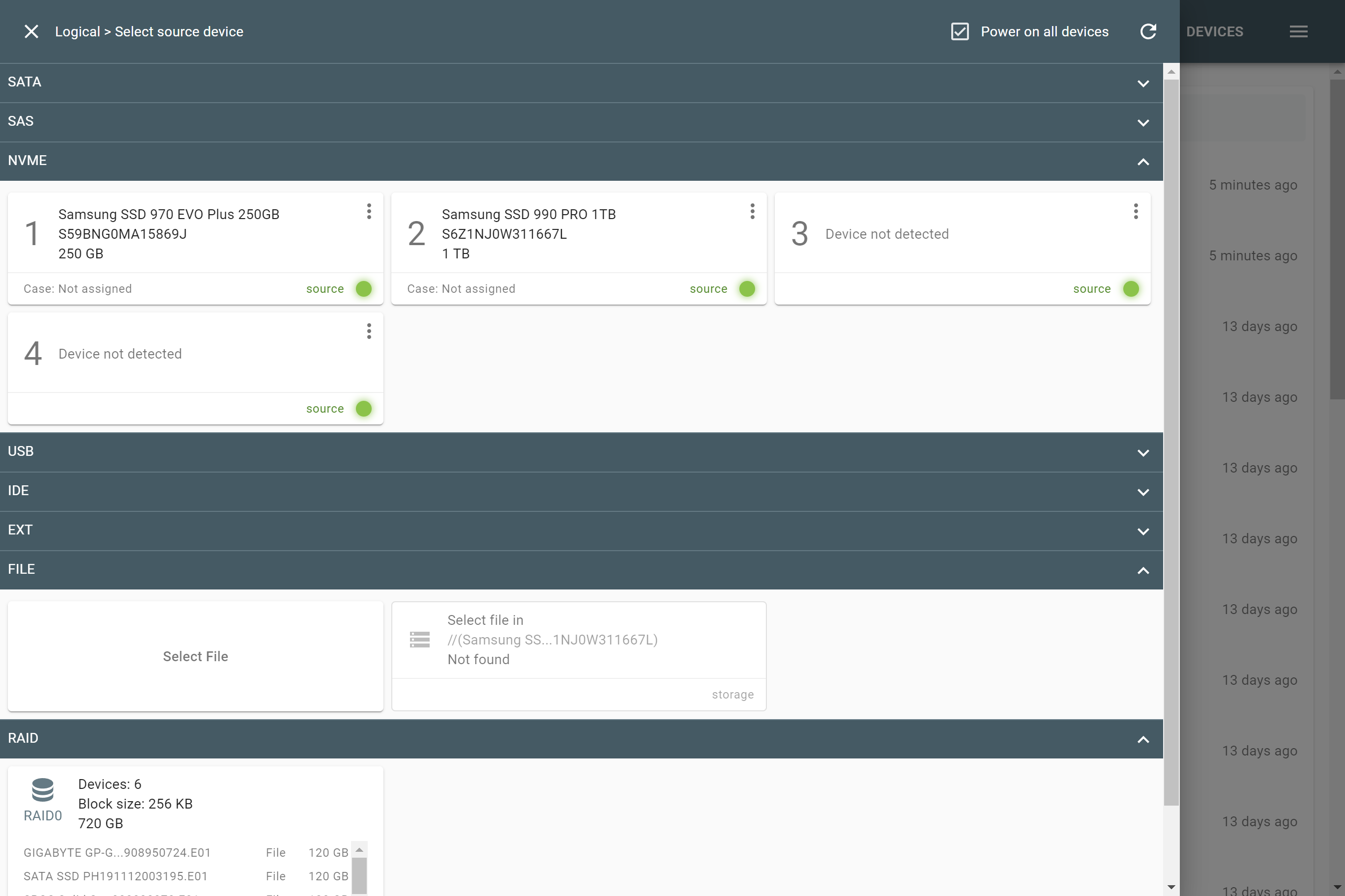
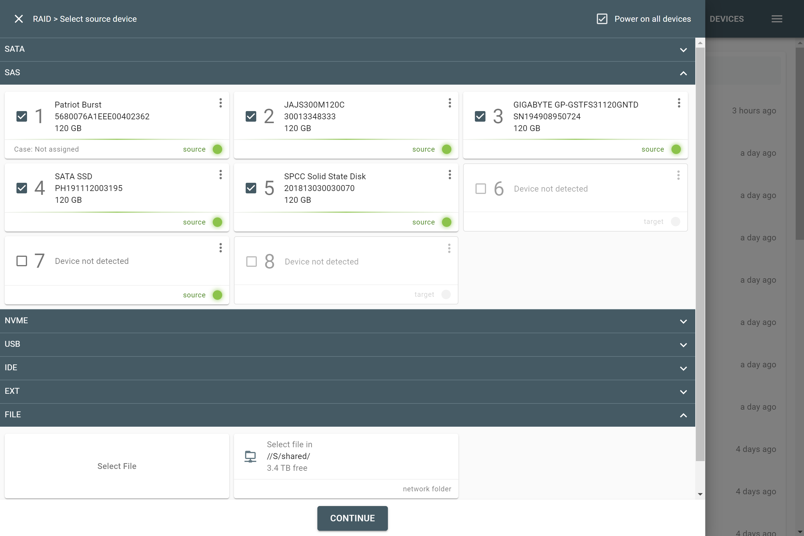
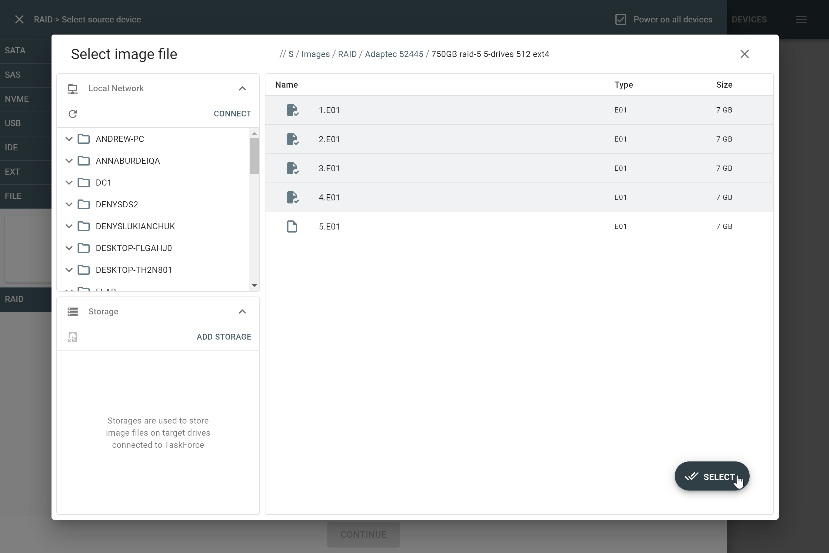
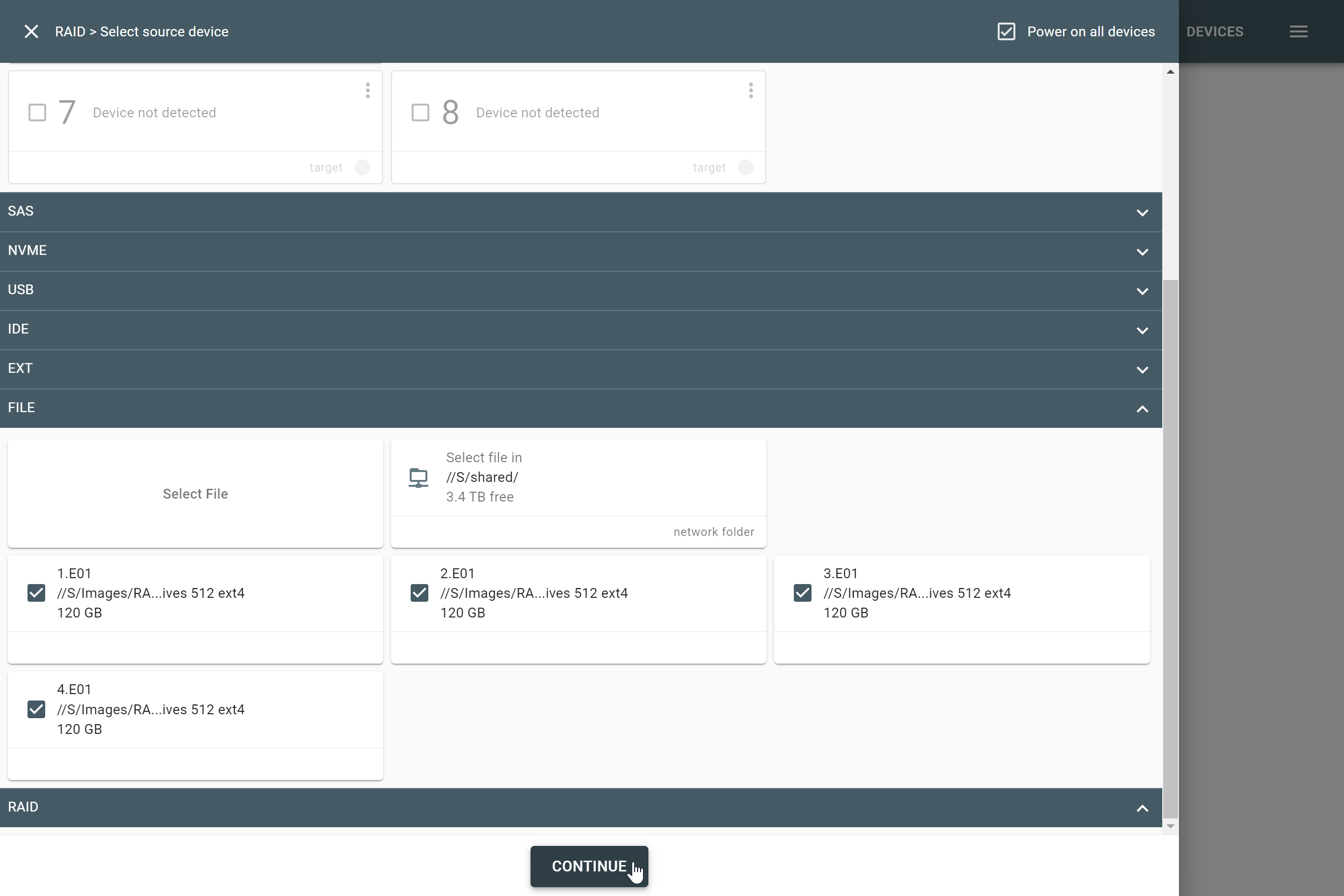
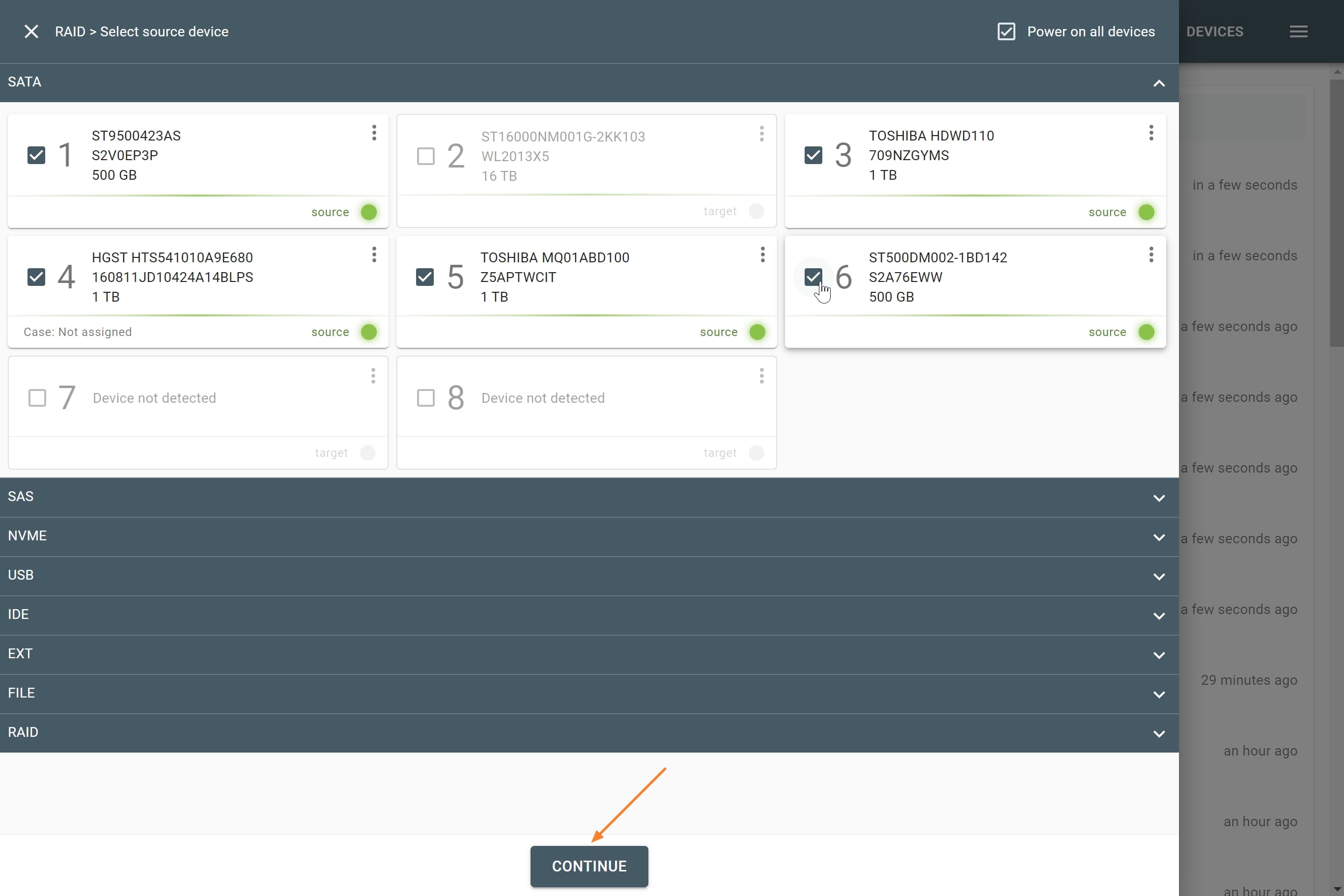
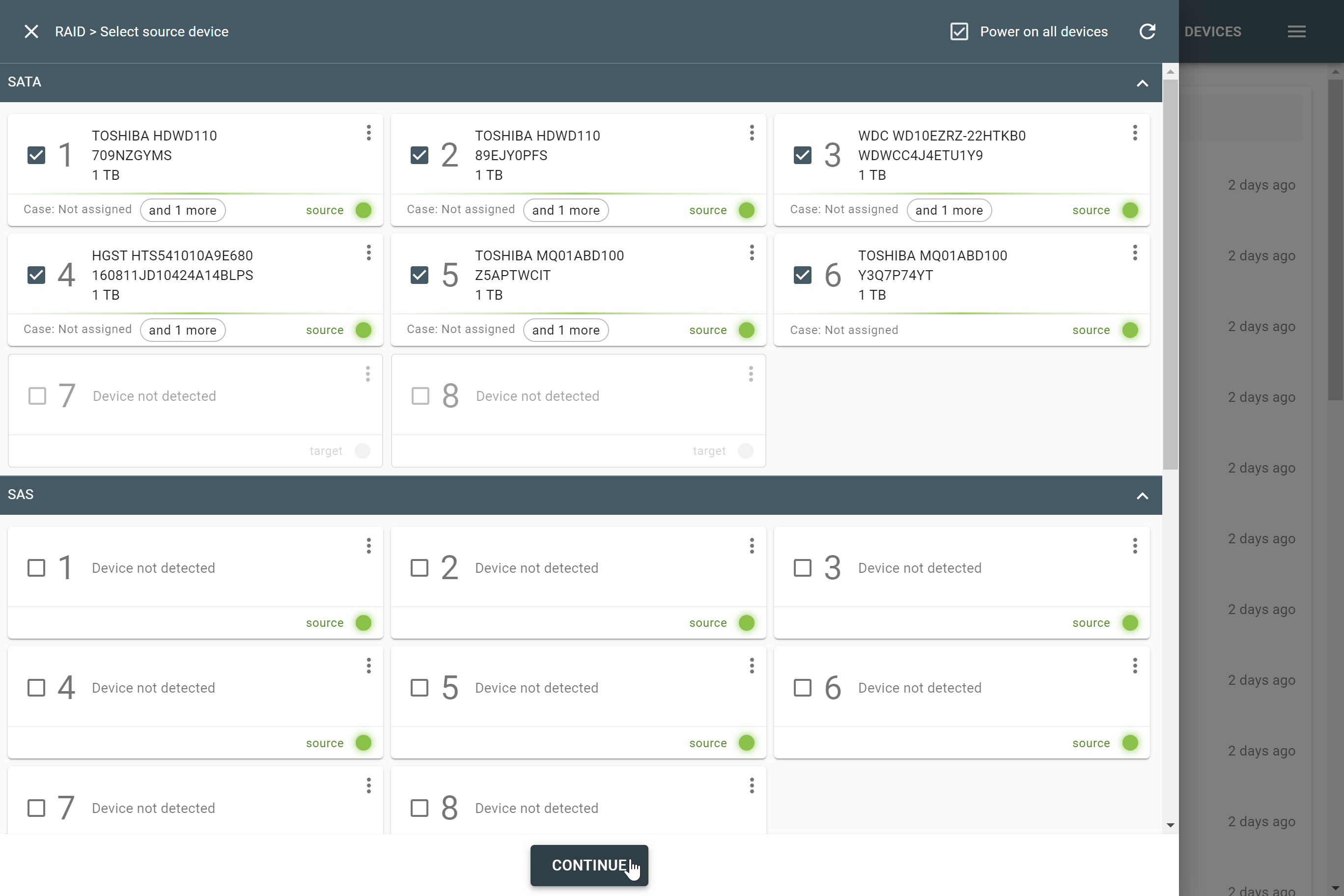
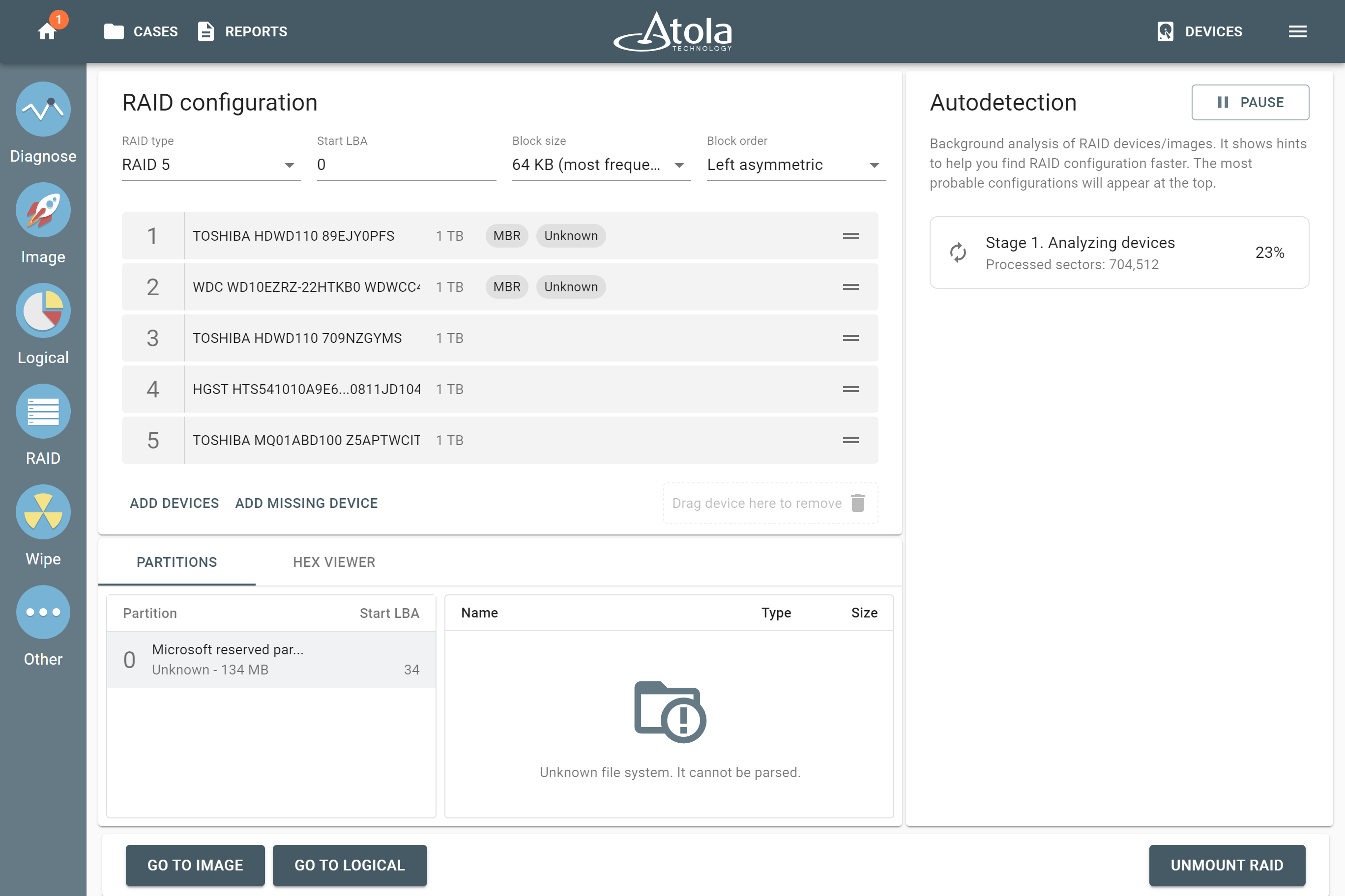
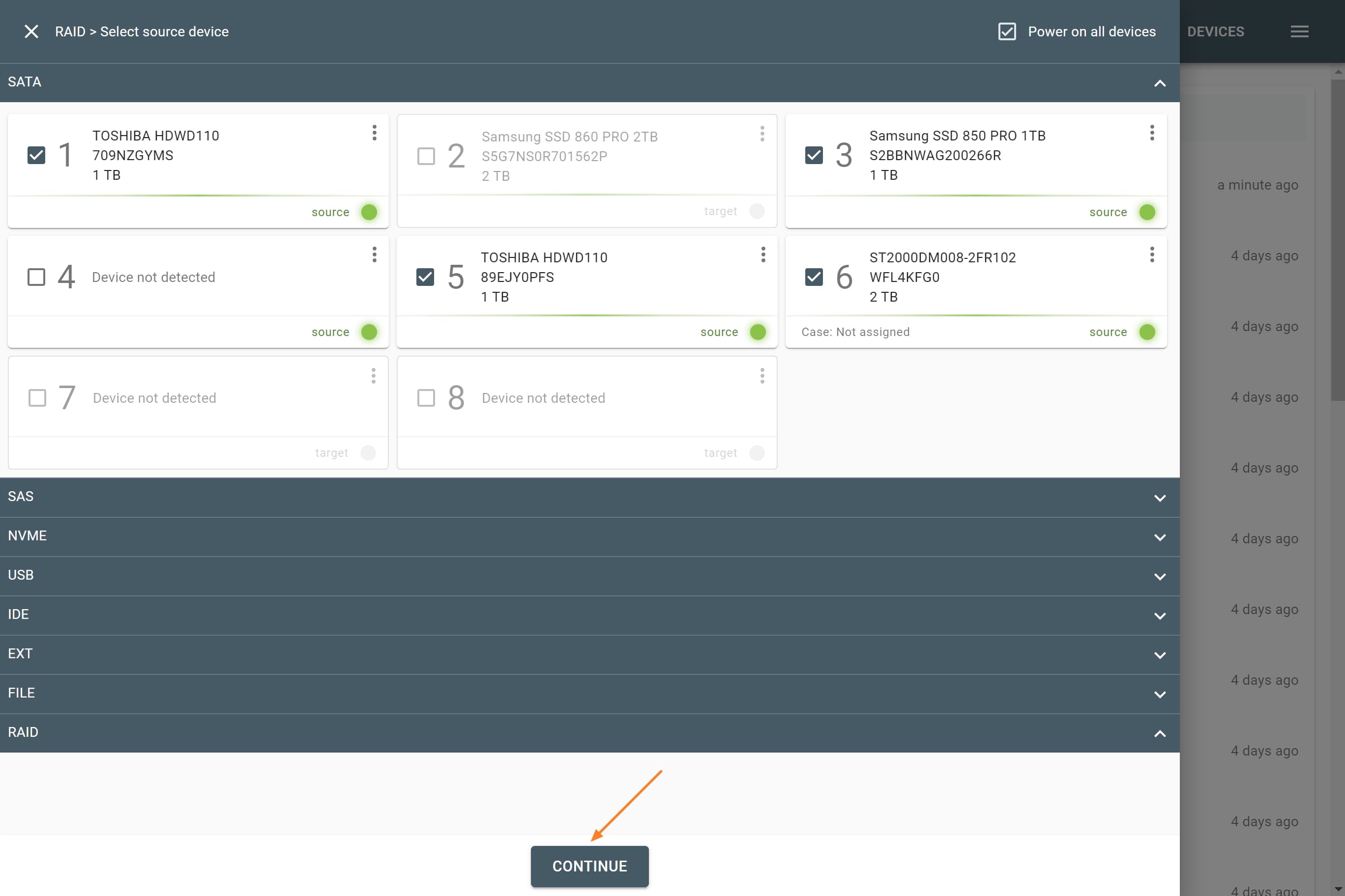
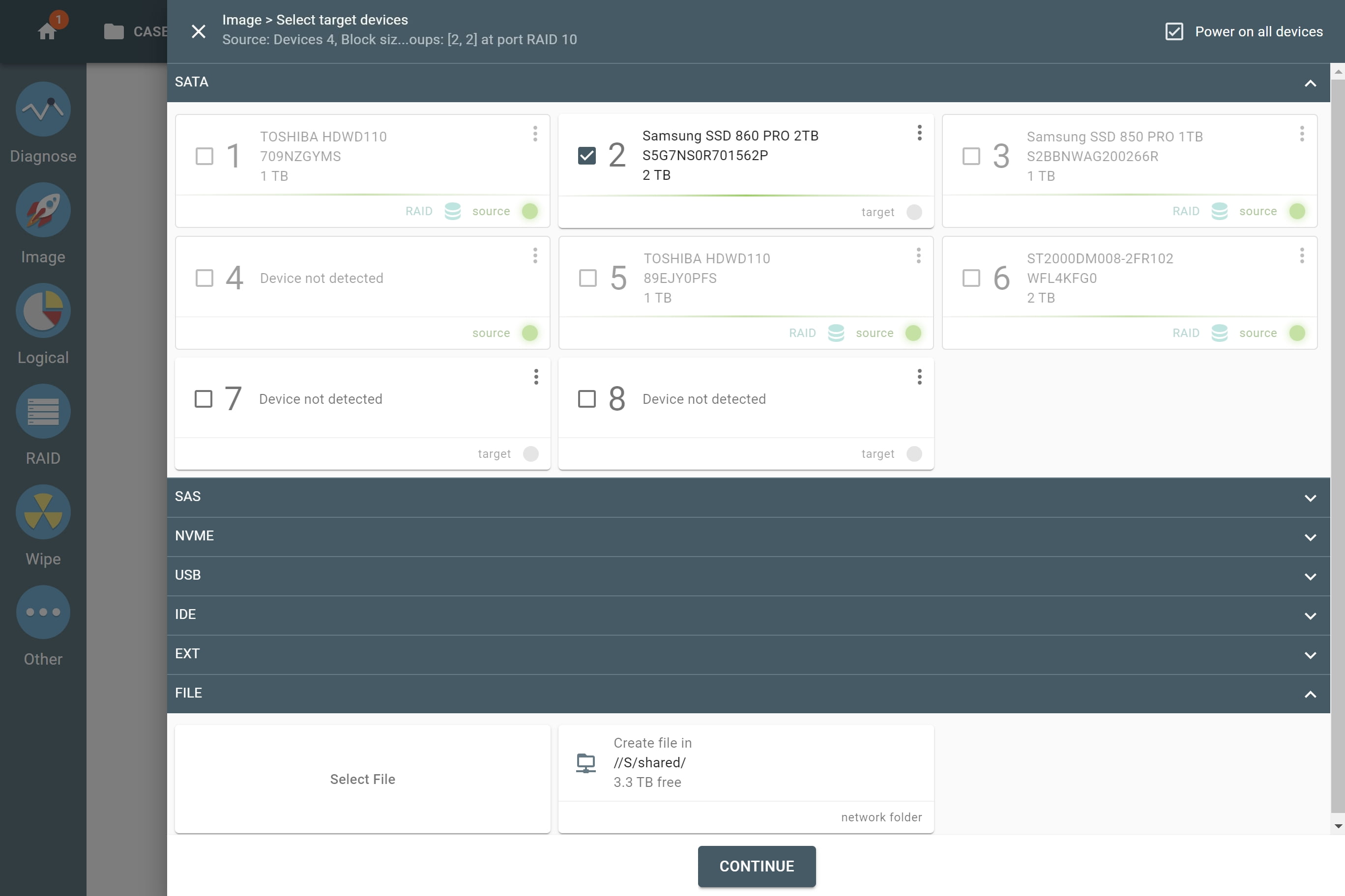
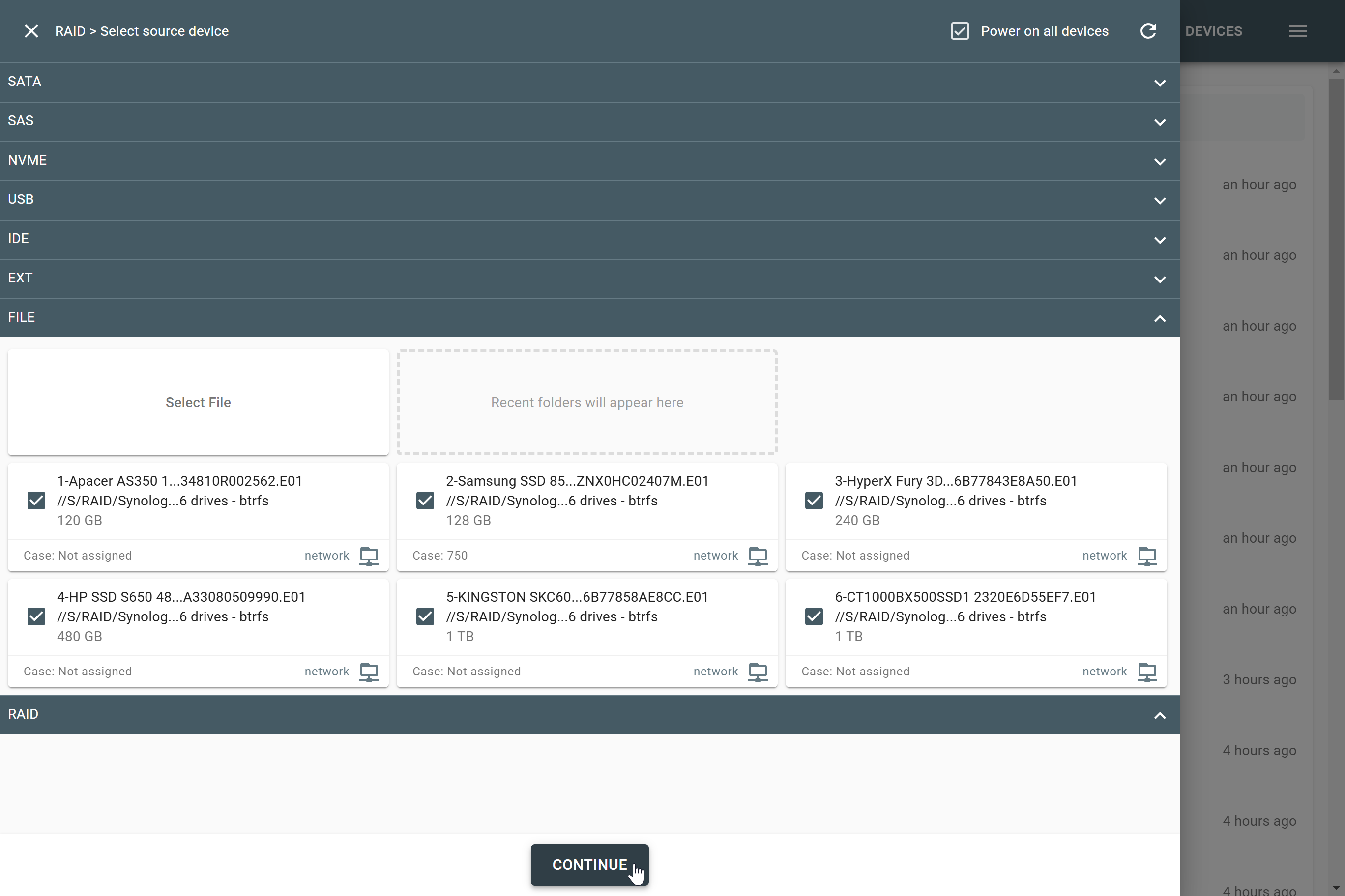
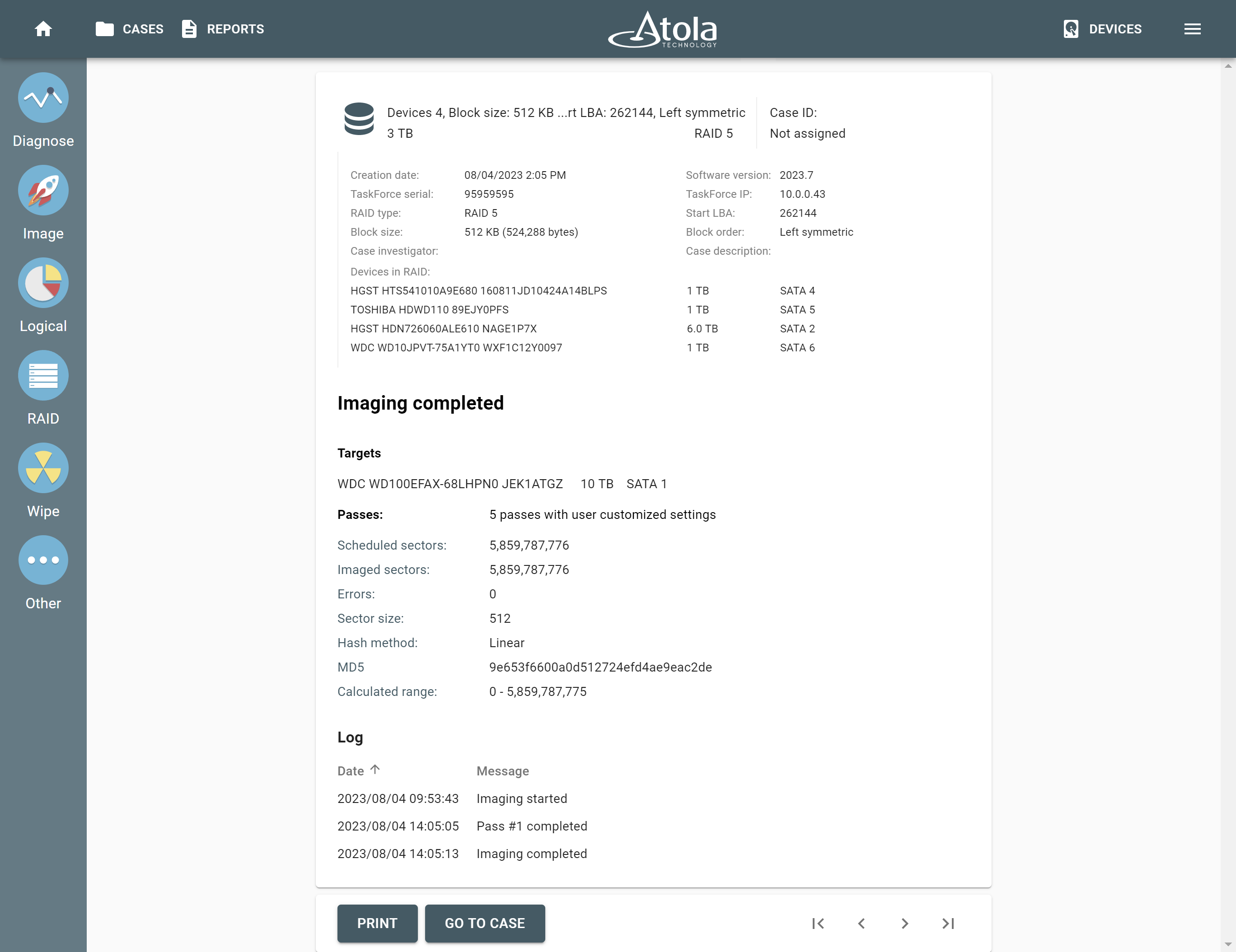
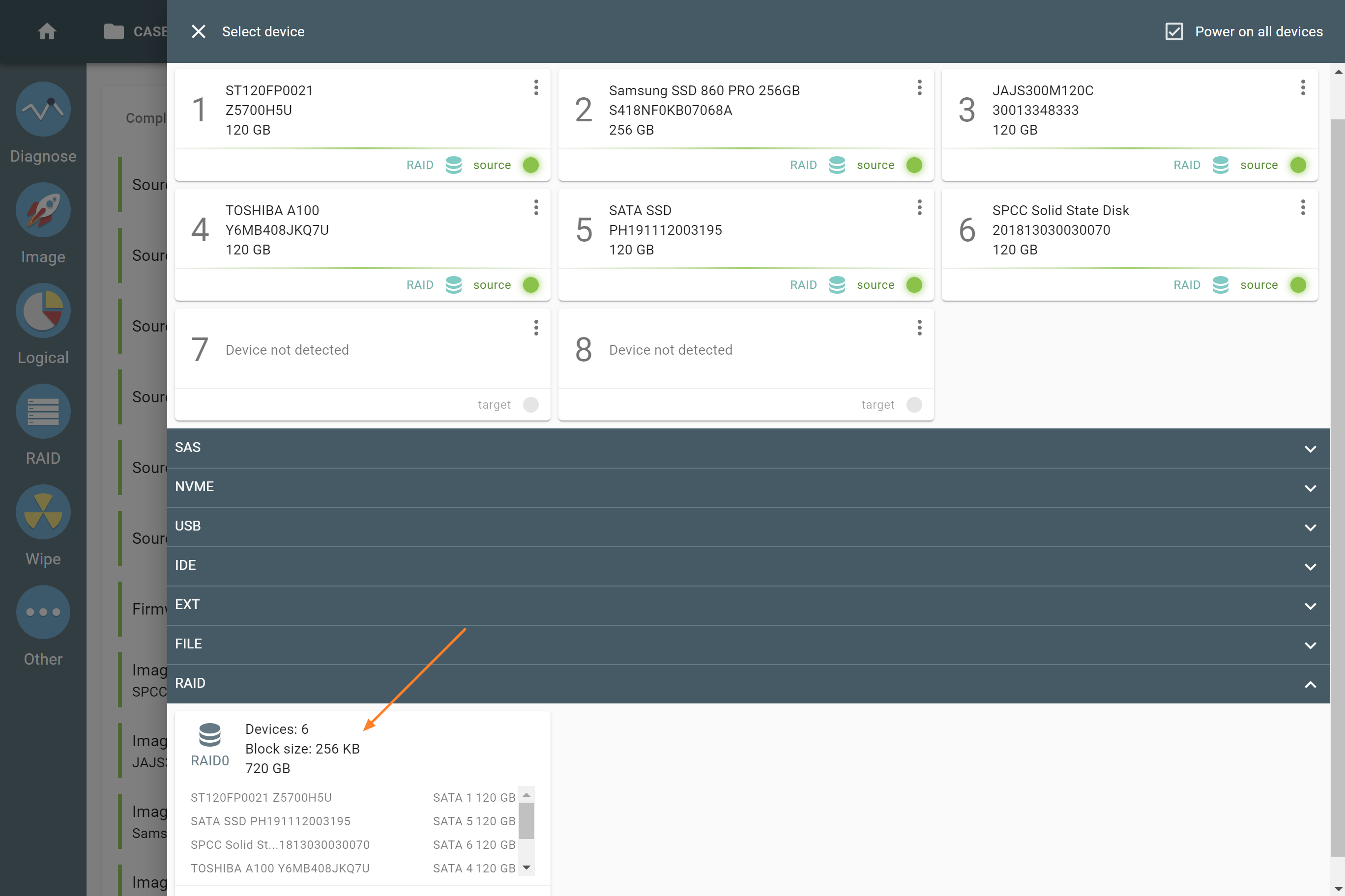
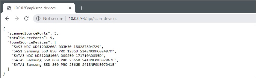
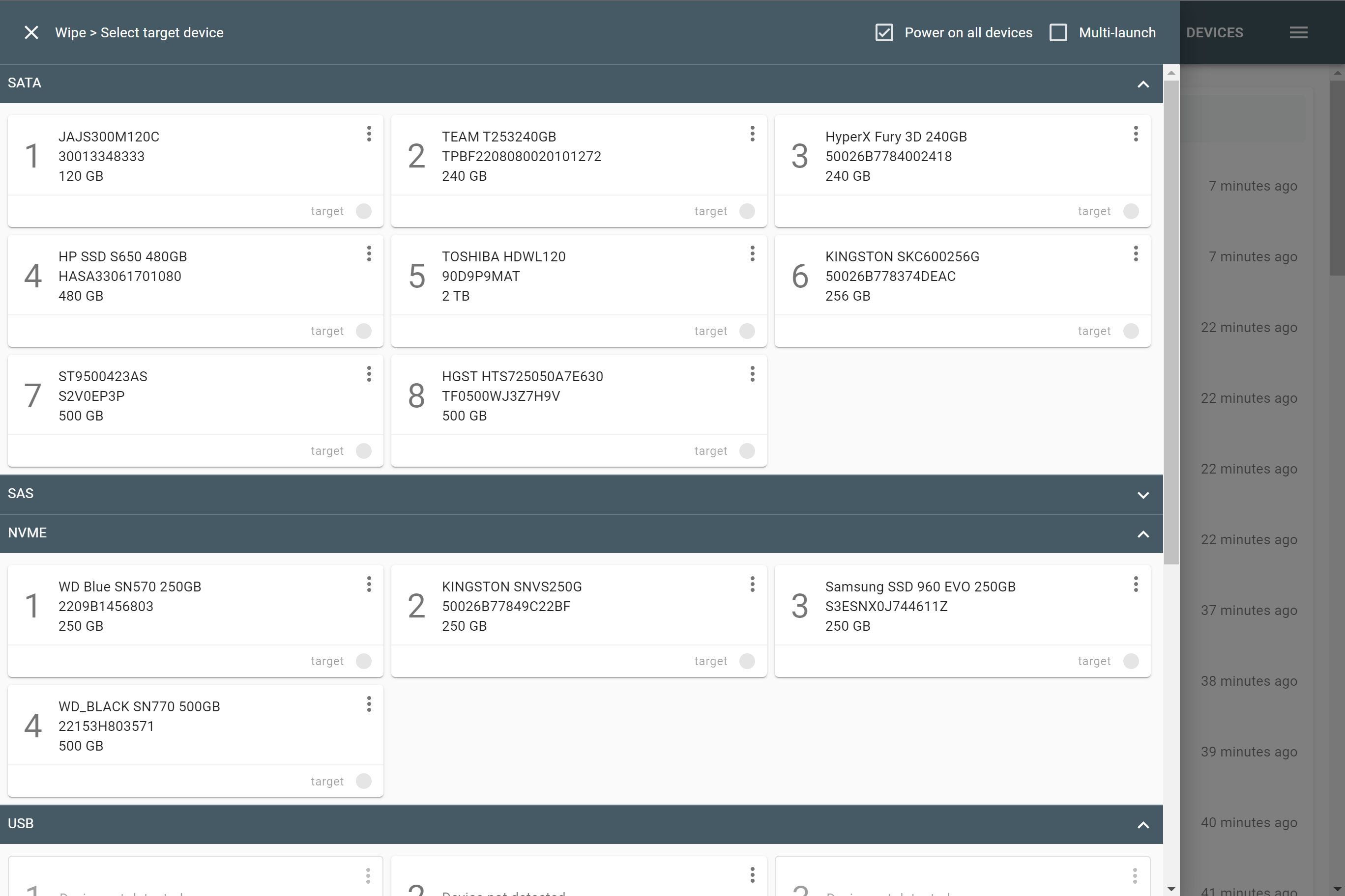
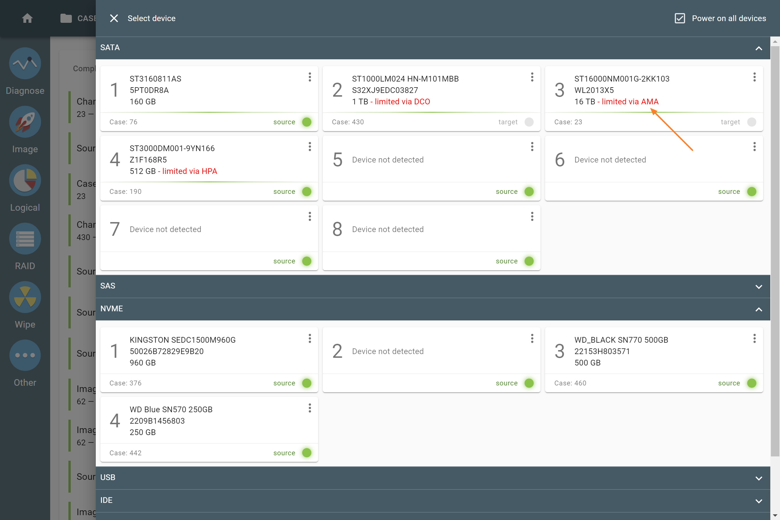
The actual number of RAID members is determined by you when you select in the TaskForce RAID module physical disks (SATA/SAS/USB drives) or their images (raw, E01 or AFF4 image files) as Sources that make up a RAID array.
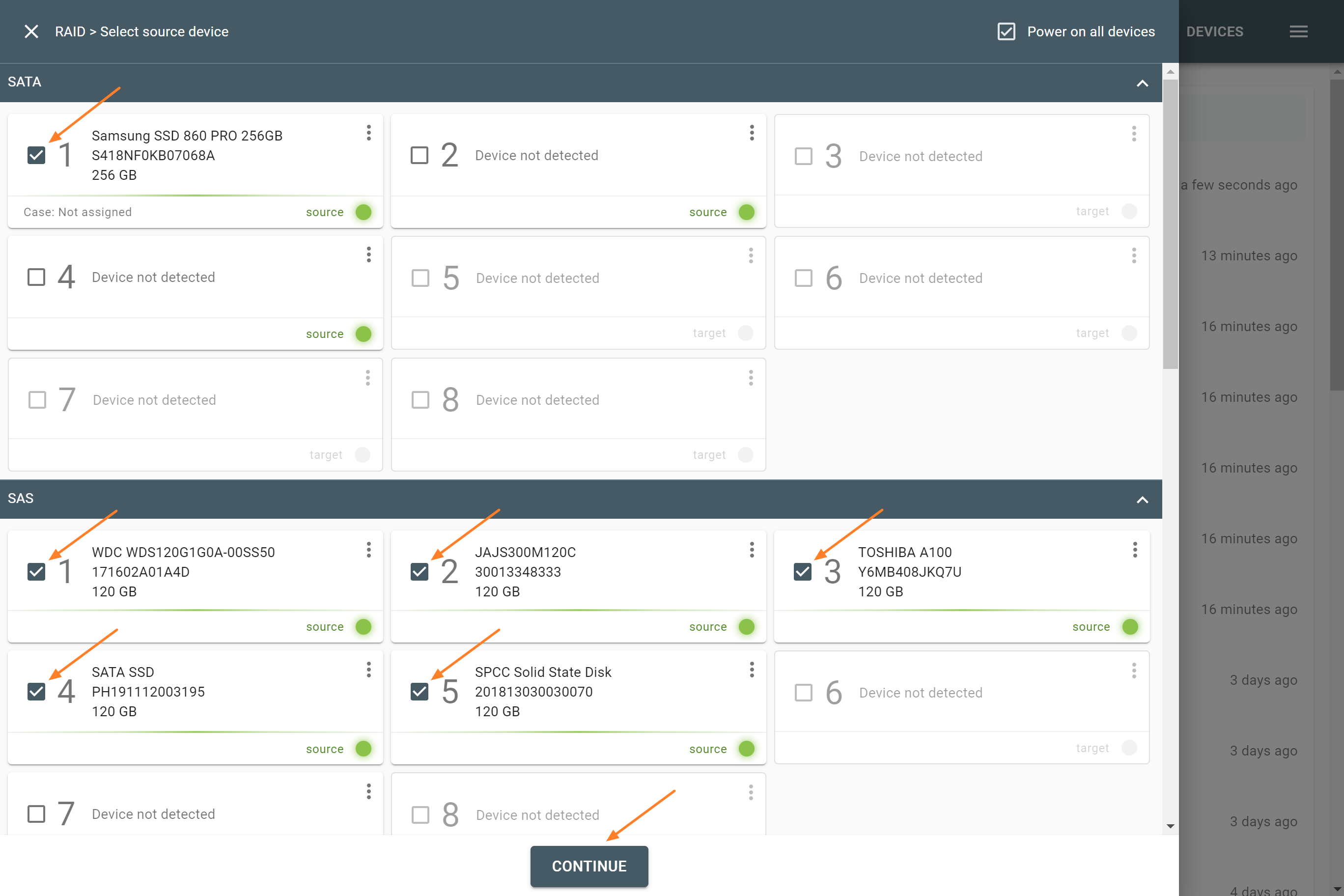
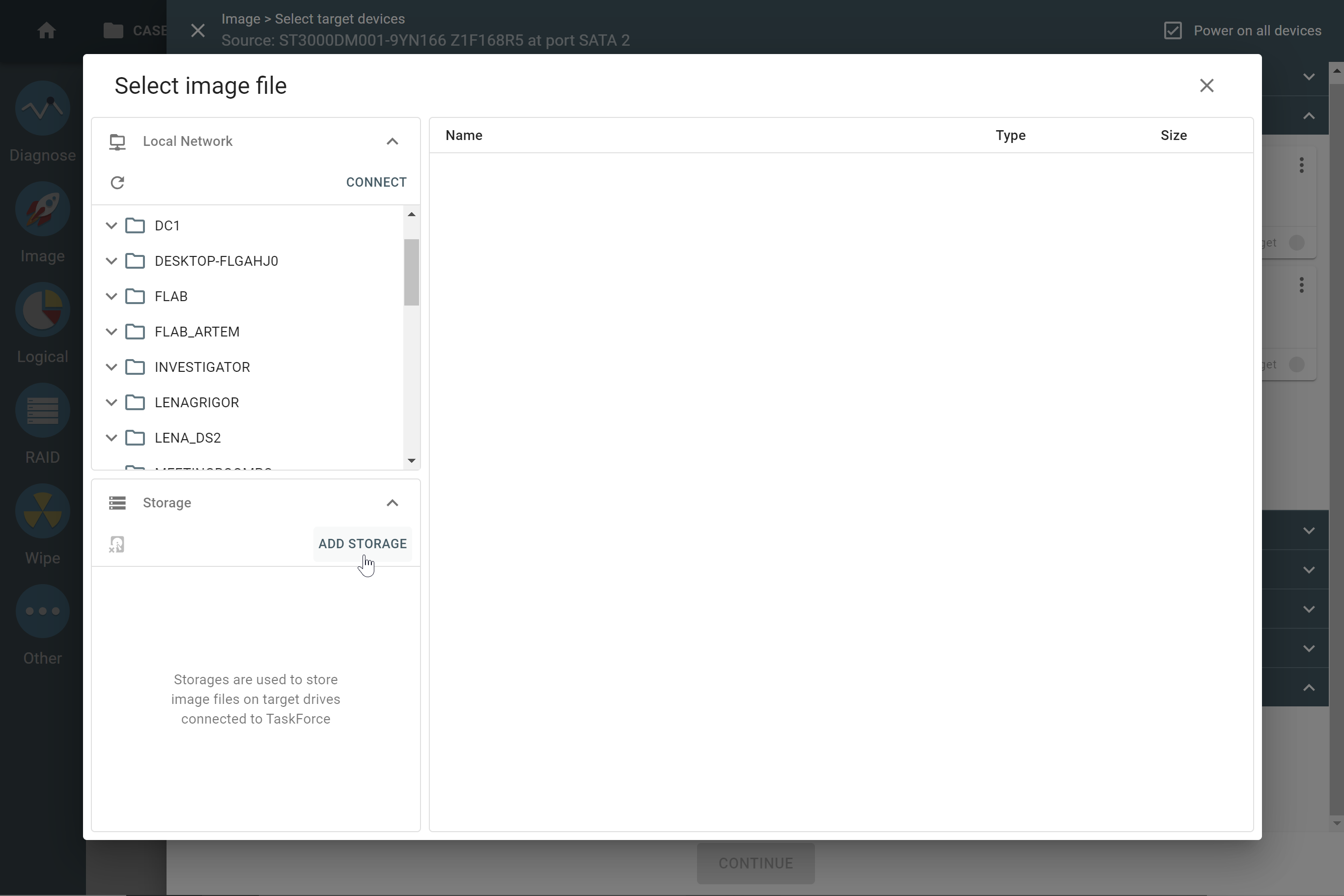
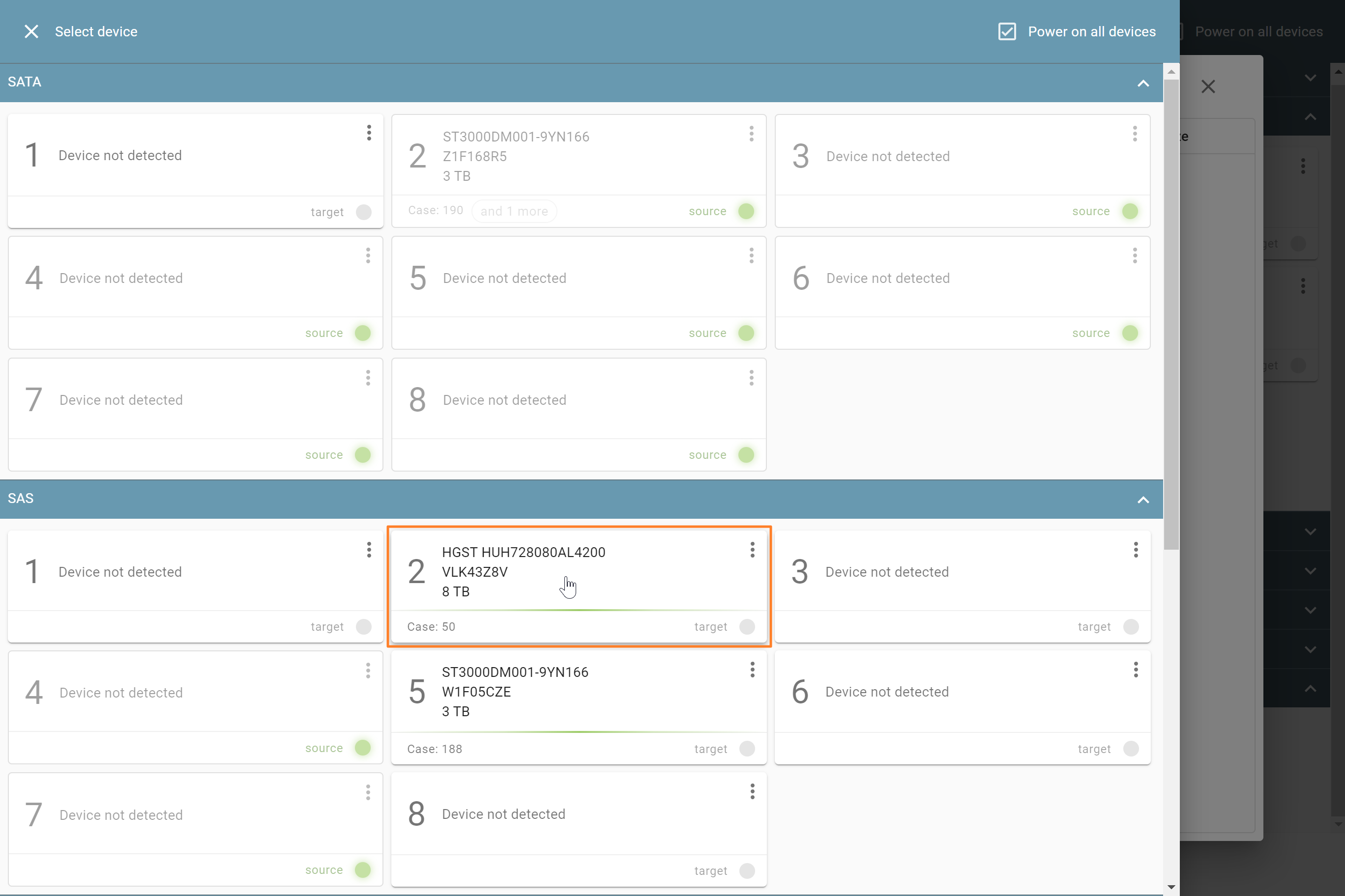
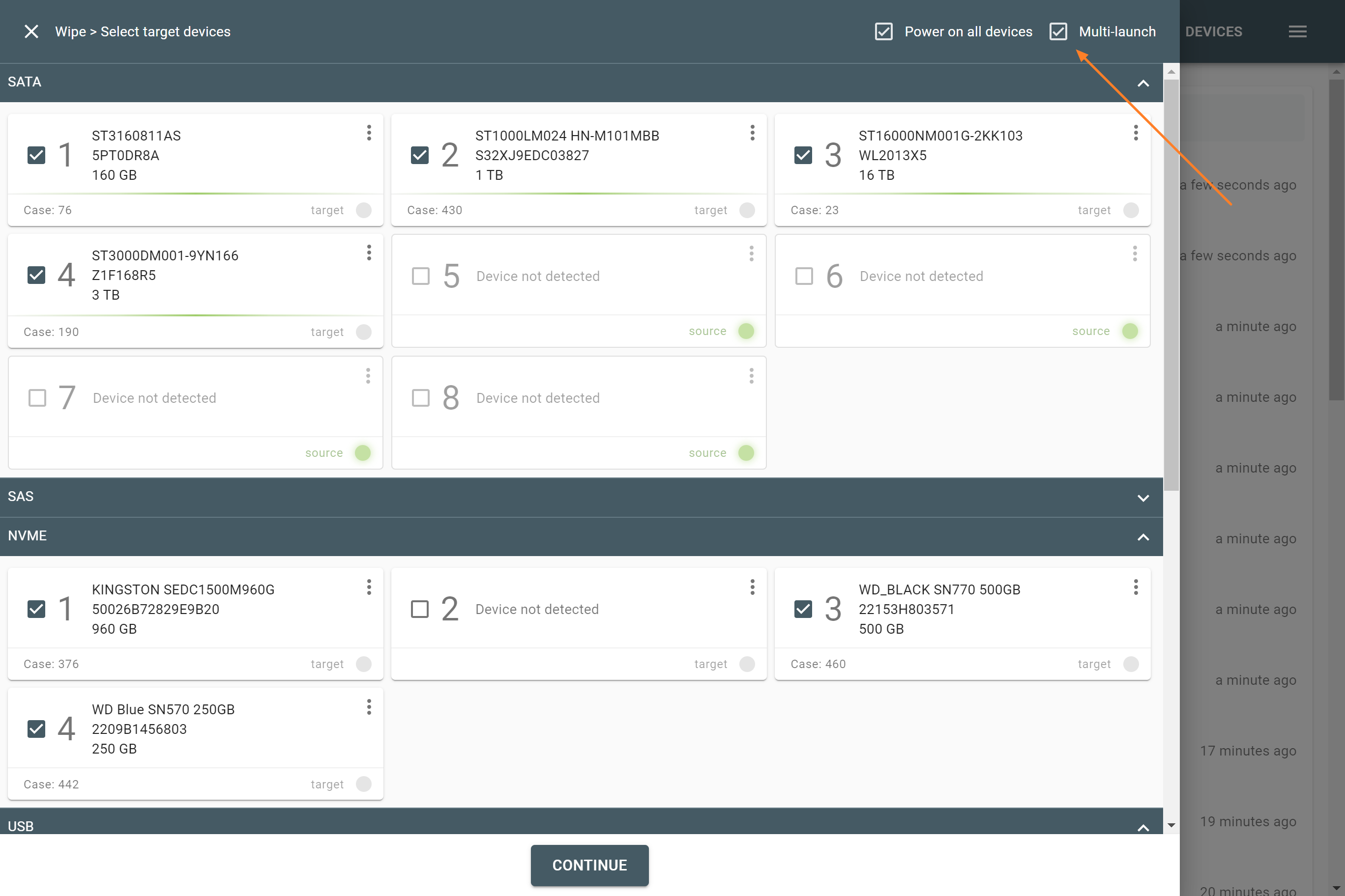
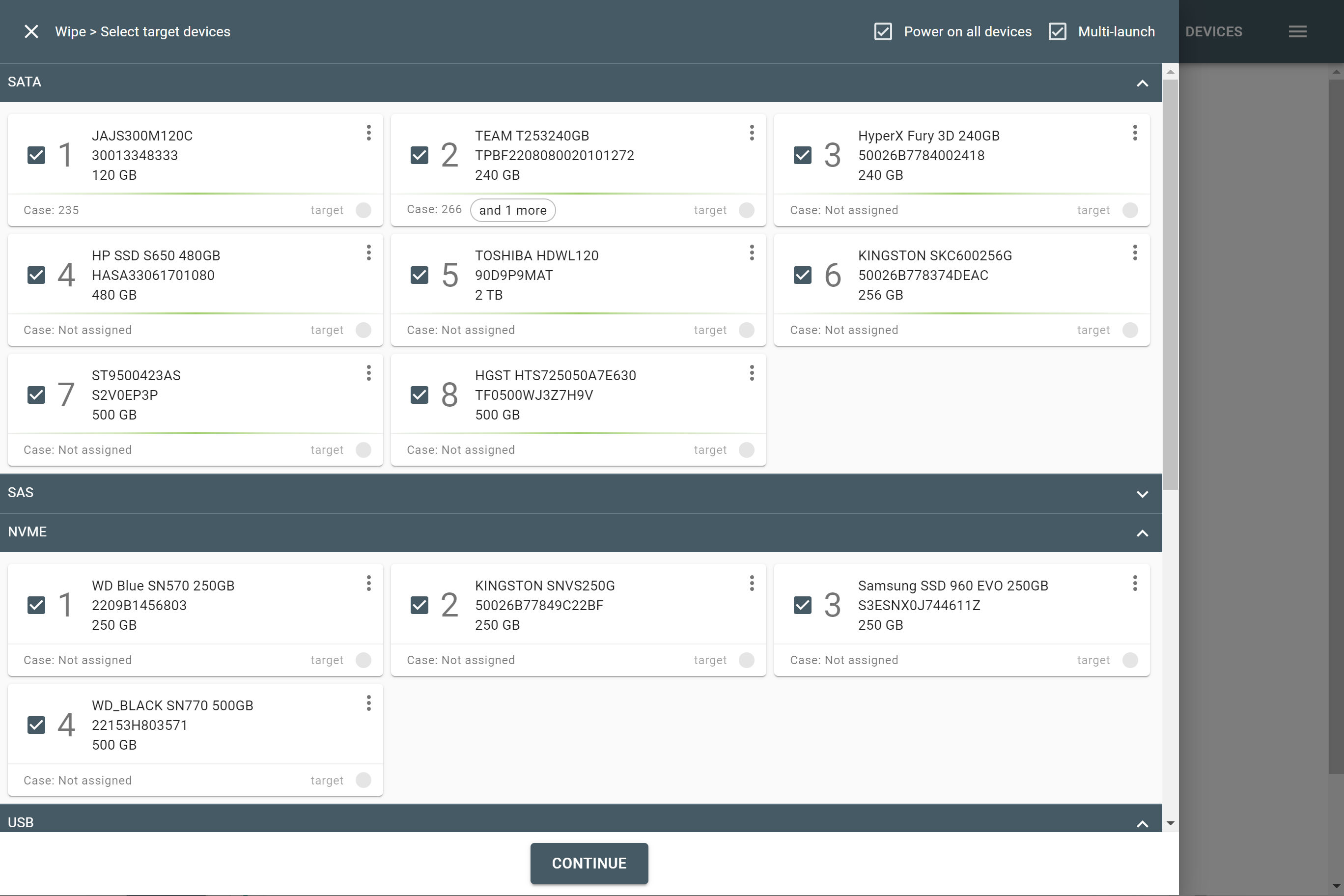
Selecting source RAID drives.
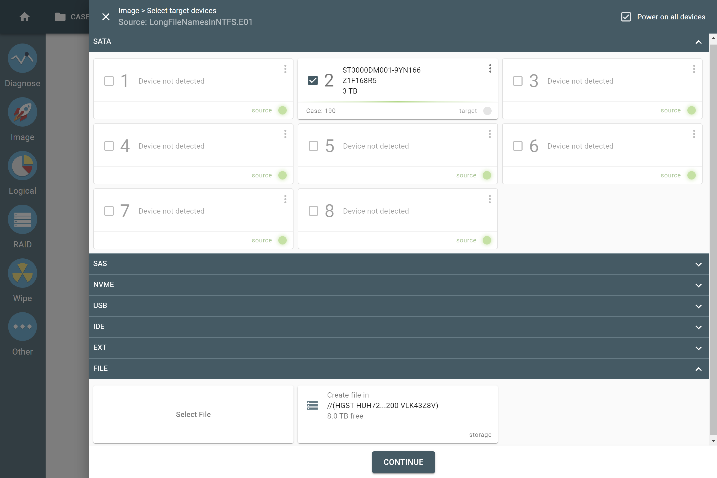
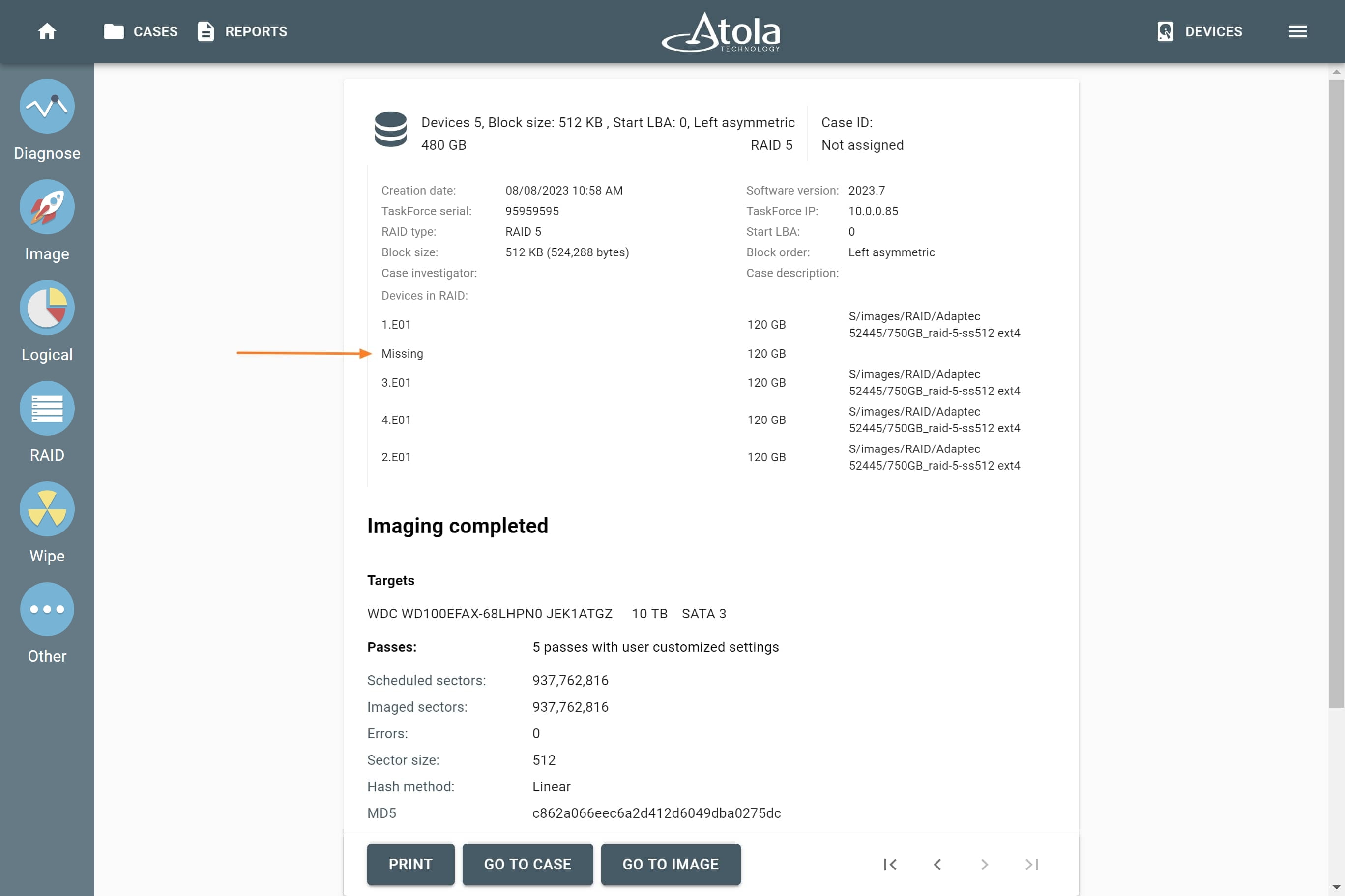
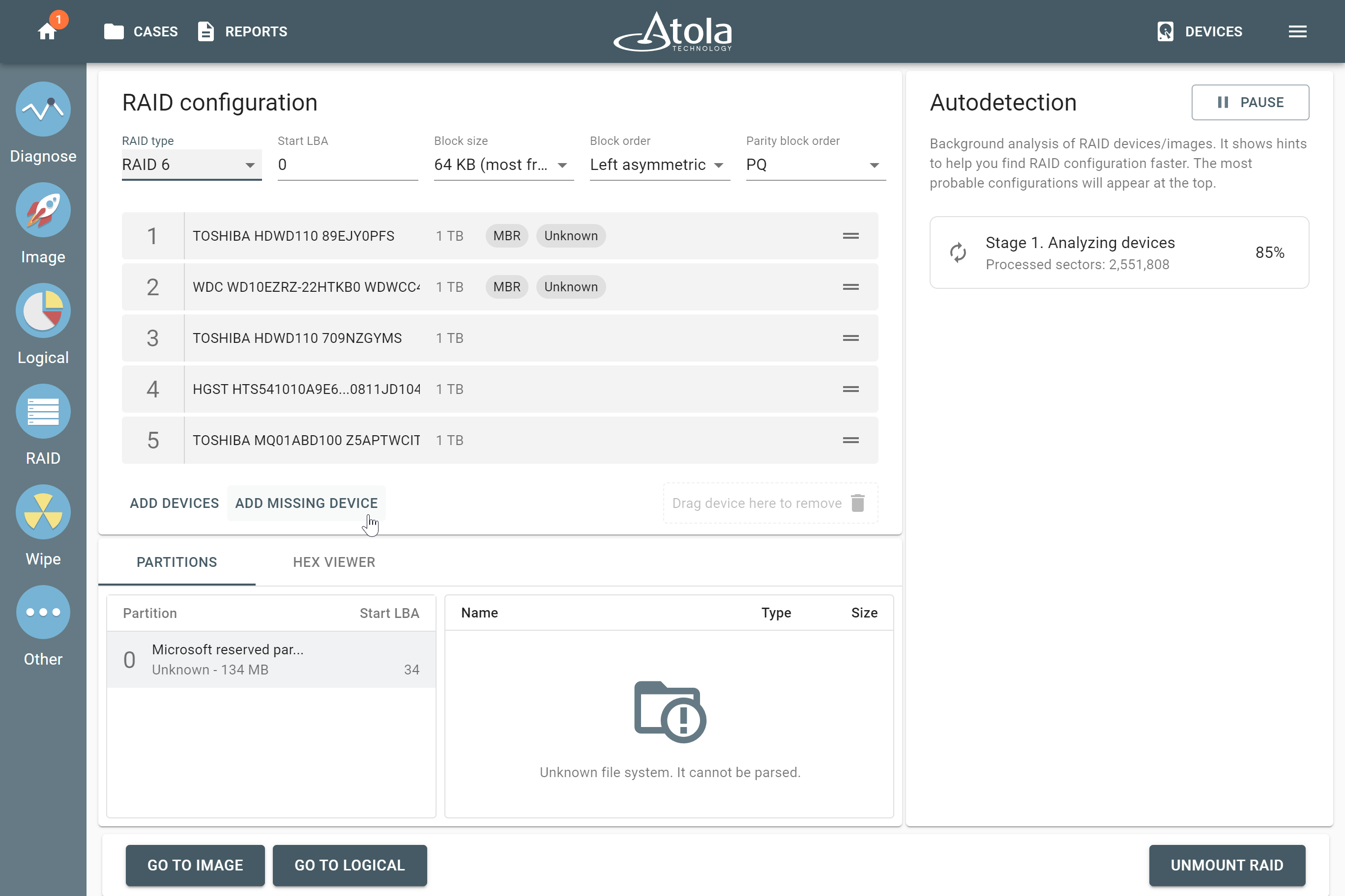
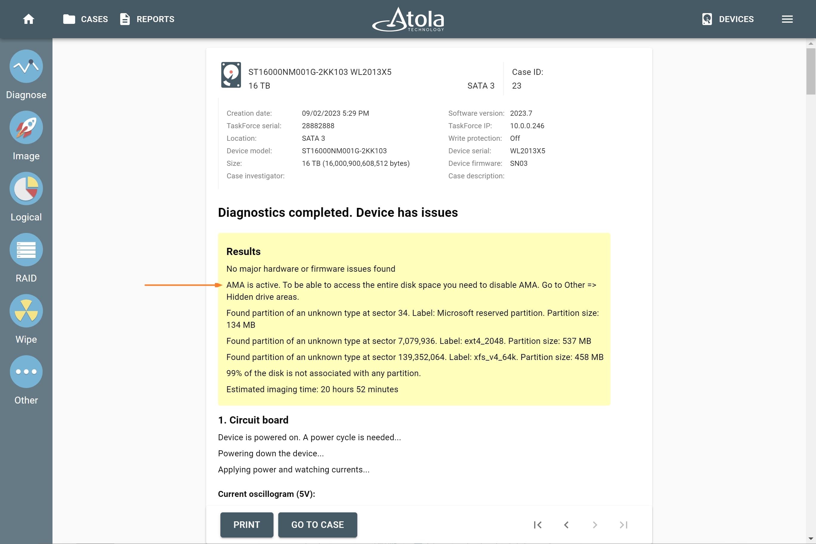
Missing RAID members. For the RAID types that use redundancy (parity blocks), TaskForce can reassemble an array and create its image even with a missing device:
- with one missing device for RAID 5 that uses distributed parity,
- with two missing devices for RAID 6 that uses double distributed parity.
See RAID 5 with a missing drive for more details.
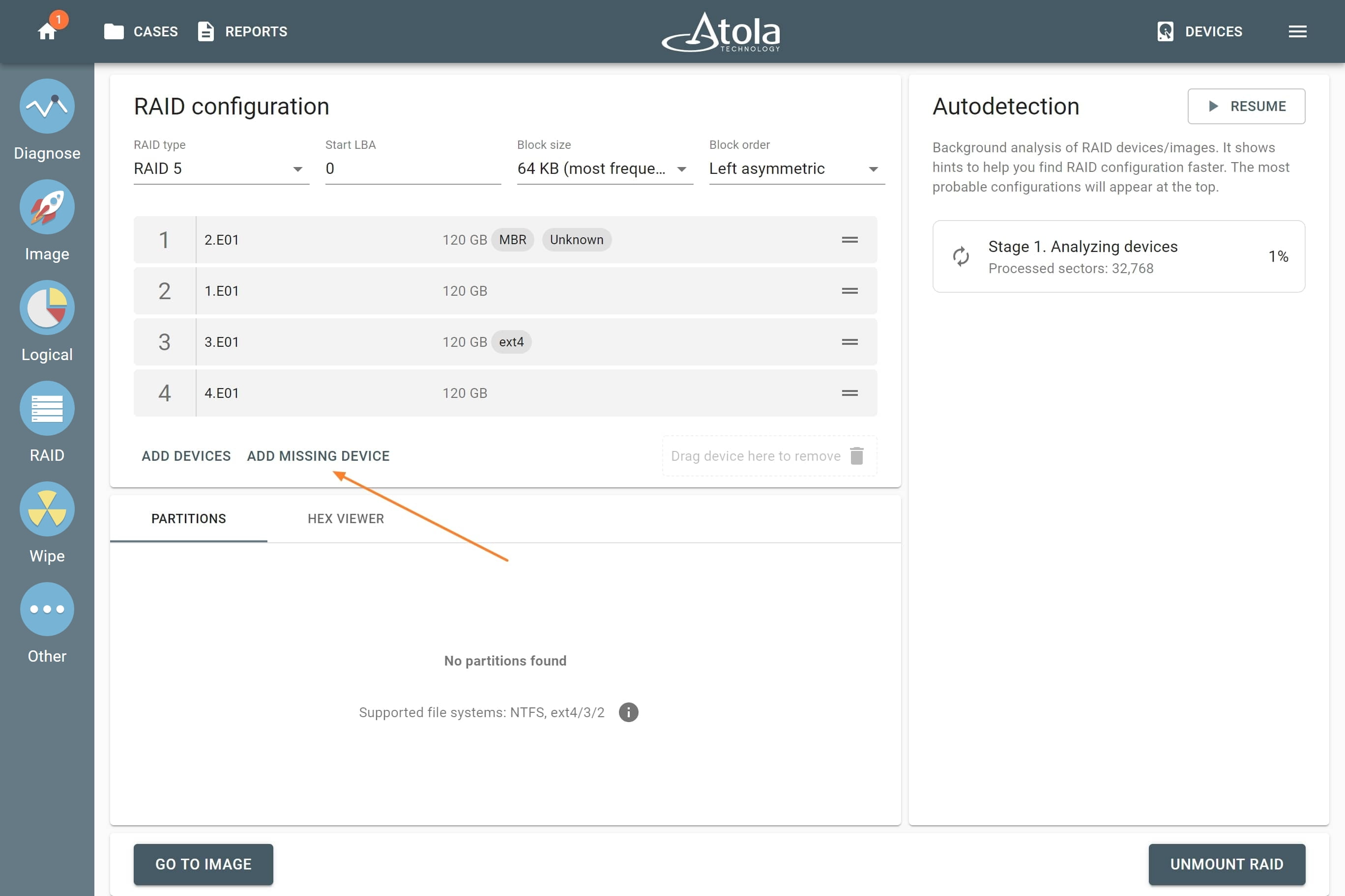
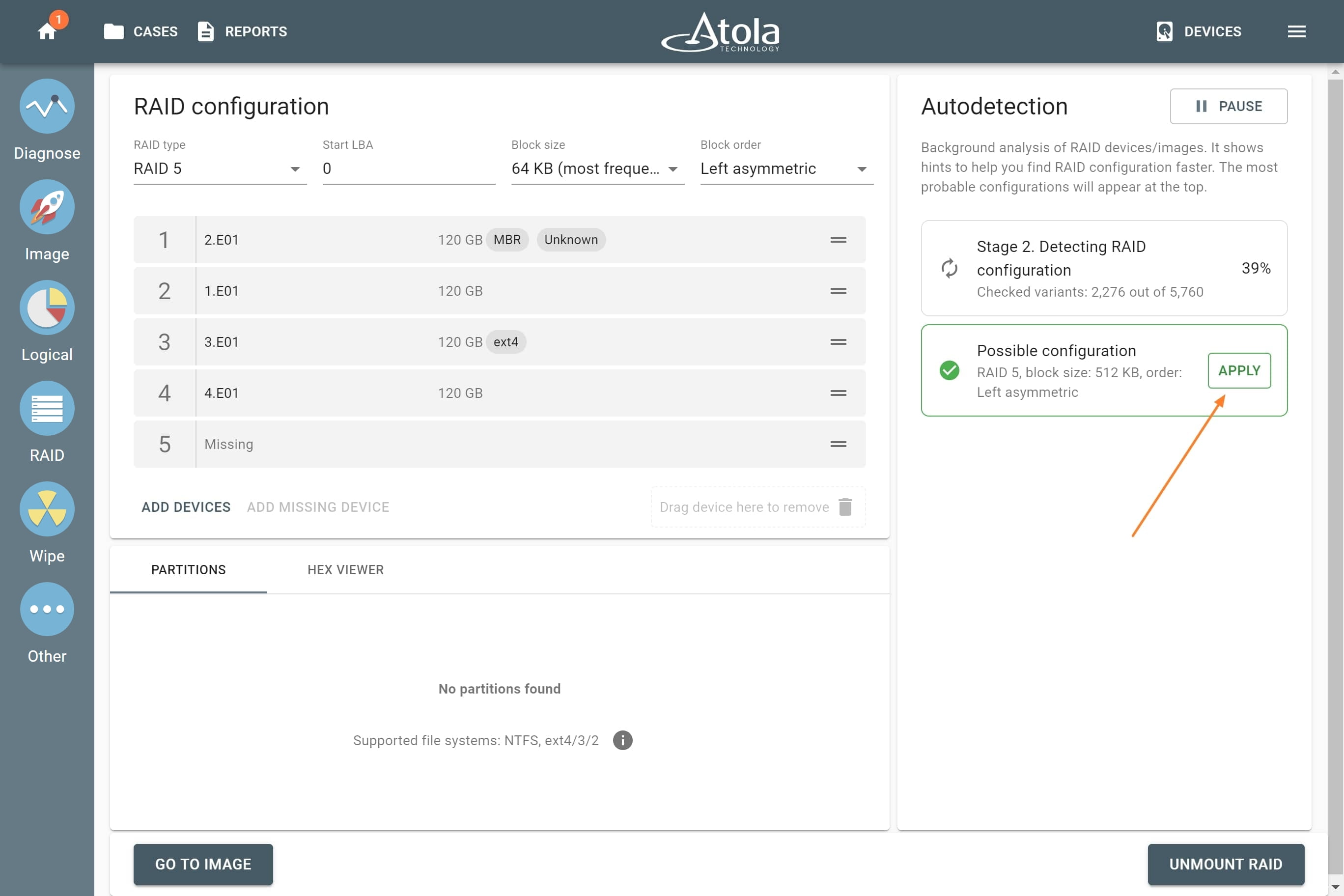
Adding missing RAID 5 drive.
Device order
Applies to: all supported RAID types.
The drive order is the order in which physical devices (or their images) follow each other within a logical array (think pages within a book). That order is defined by a RAID controller during the setup of an array. To reassemble and image a RAID array, you need to determine which of its members go first, second, third and so on.
In TaskForce, the drive order can be automatically detected by the Autodetection module along with other parameters.
However, if you know the drive order, arrange the RAID members manually by dragging them up or down in the RAID configuration section of the TaskForce RAID module.
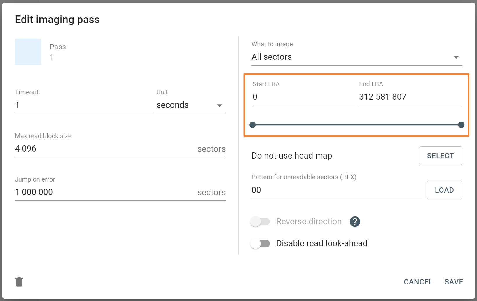
Start LBA (or Disk offset)
Applies to: all supported RAID types.
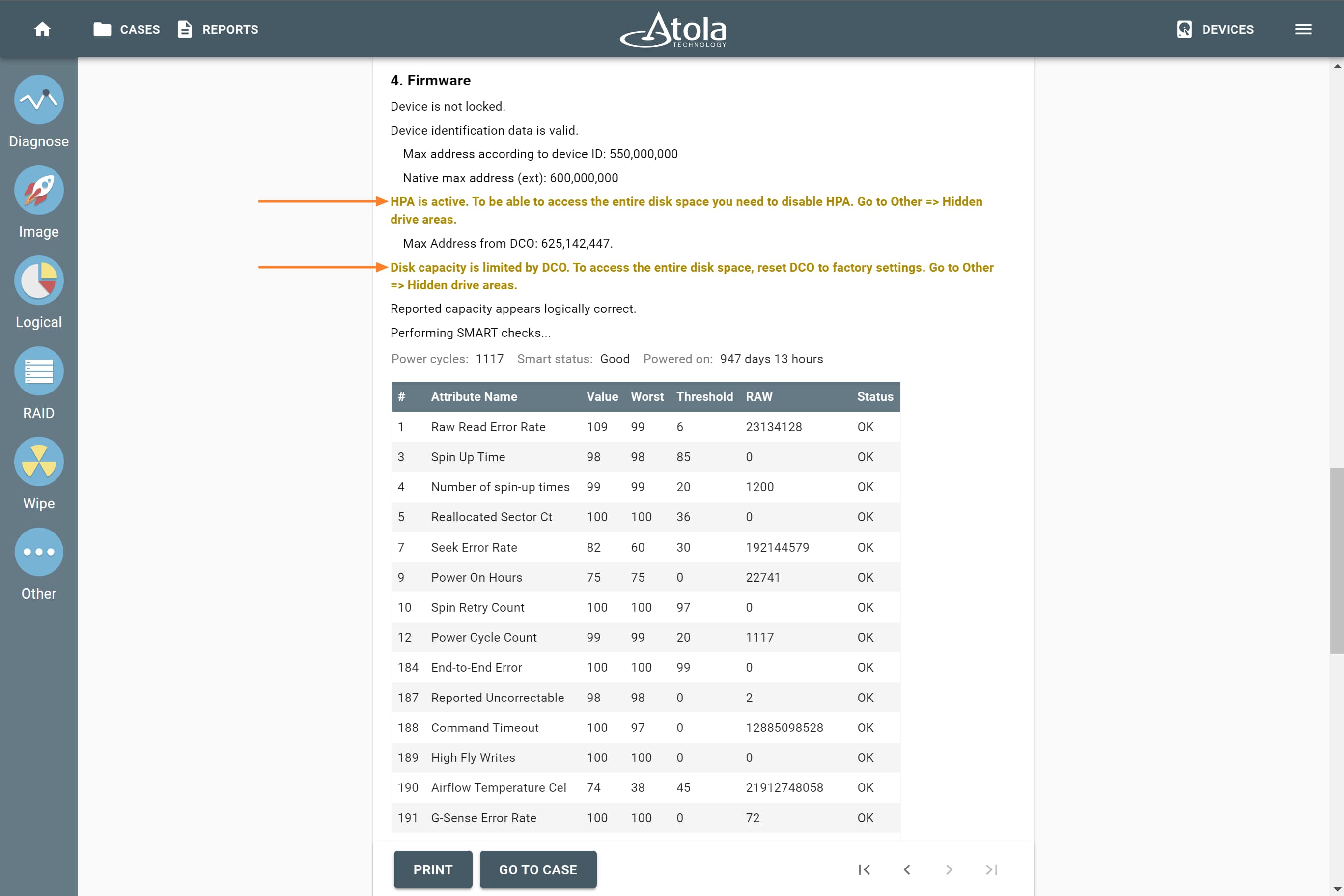
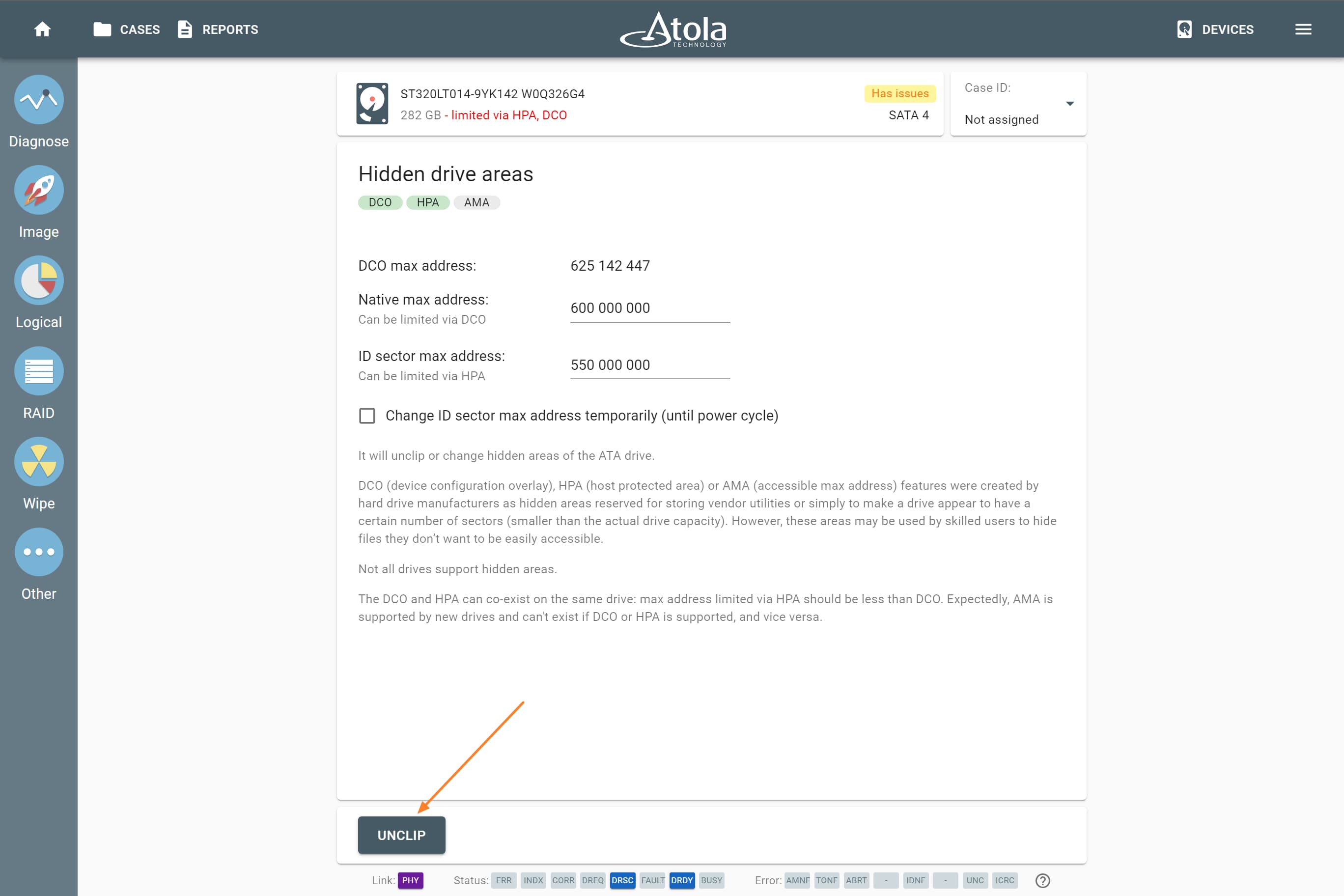
LBA stands for Logical Block Address. It is a scheme used for addressing a particular area on a storage device in a linear way using sequential integer numbers, starting from zero: 0, 1, 2, 3… Thanks to LBA a single drive or a RAID controller identifies the exact location of bytes it needs to read from or write to.
When we talk about RAIDs, Start LBA, also known as Device offset, refers to an address of a logical block on each physical RAID member where user data begins. Start LBA of each member of the same RAID is identical.
If RAID’s Start LBA is 0, RAID blocks (chunks) start from the first logical block on each drive in an array, without any offset (it is the most common case).
If RAID’s Start LBA is greater than 0, a space created by this offset is skipped. RAID blocks start from the specified Start LBA on each drive in an array. Typically, the skipped space can be used to store RAID metadata (data about data).
In some cases, TaskForce can identify RAID’s Start LBA during autodetection using a heuristic algorithm.
If you know Start LBA, you can enter it in the Start LBA field of the RAID configuration section.
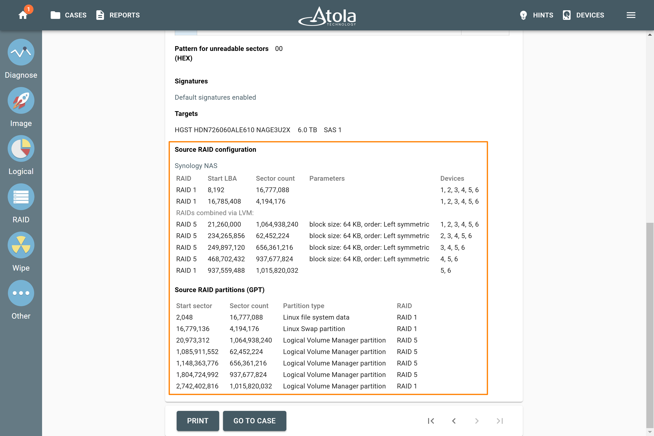
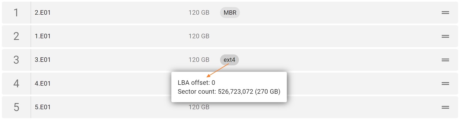
When we talk about logical partitions, Start LBA refers to the logical block address where a particular partition starts in an already assembled RAID array. In this case, Start LBA of each partition is different.
Block size
Applies to: RAID 0, RAID 10, RAID 5, RAID 6 (types that use striping method).
Some RAID types use striping method for distributing data across physical drives: data is split into consecutive logical blocks (also called “stripes” or “chunks”), which are stored on different physical storage devices.
The Block size parameter in TaskForce RAID module refers to the size of these logical blocks (or “stripes”) measured in bytes. TaskForce supports RAID block sizes from 512 bytes to 1 megabyte and can detect that parameter automatically using a heuristic algorithm. The most frequently used block size is 64 kilobytes.
If you know the block size of a RAID, you can select it manually from the Block size list in the RAID configuration section.
Block order
Applies to: RAID 5, RAID 6 (types that use block-level striping with distributed parity).
The Block order parameter defines the layout (or pattern), in which RAID logical blocks (“stripes”) are distributed among the devices in the array. It is the sequence of writing data and parity blocks across the RAID members and depends on:
- The direction of data blocks writing: left to right or right to left on the disk array.
- The placement of the parity blocks: at the beginning or the end of the stripe.
- The location of the first block of a stripe relative to the parity of the previous stripe.
For RAID 5, the Block order parameter can be:
-
Left symmetric. This is the default RAID 5 layout under Linux.
-
Left asymmetric. This is the 'standard' RAID 5 layout.
-
Right symmetric.
-
Right asymmetric.
For RAID 6, the Block order parameter can be following:
Parity block order
Applies to: RAID 6.
Unlike RAID 5, RAID 6 uses not one, but two types of parity blocks. The Parity block order parameter defines, which parity block type comes first and which follows:
- PQ: XOR parity block comes first, Reed-Solomon parity block comes second.
- QP: Reed-Solomon parity block comes first, XOR parity block comes second.
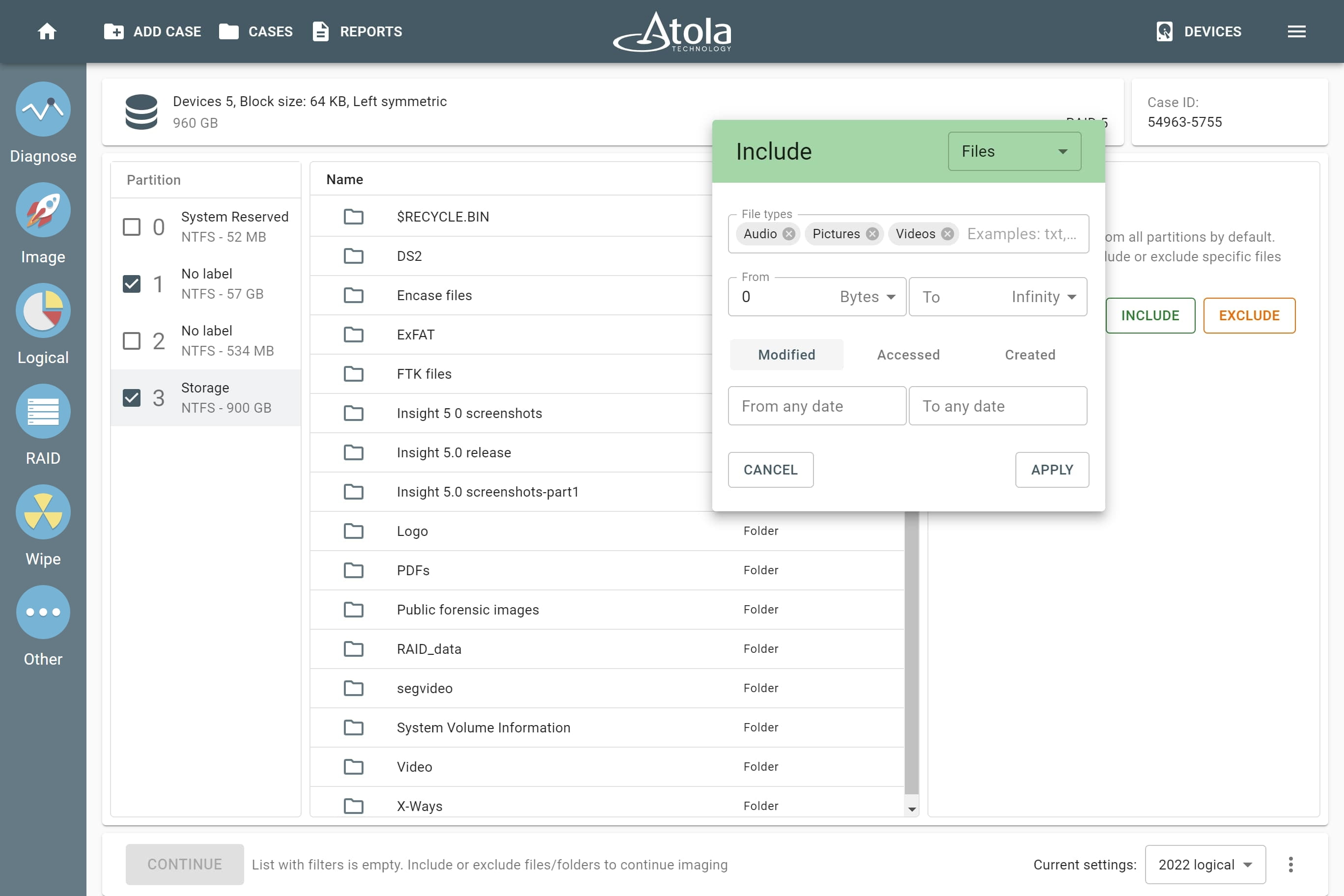
File system
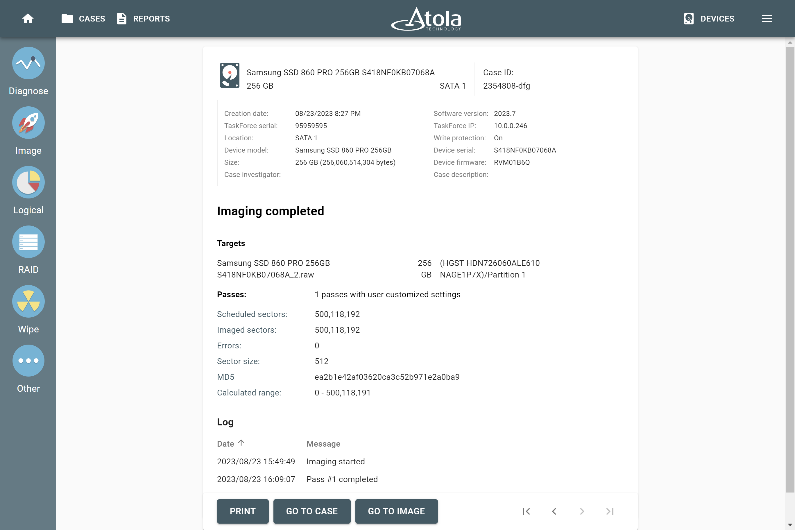
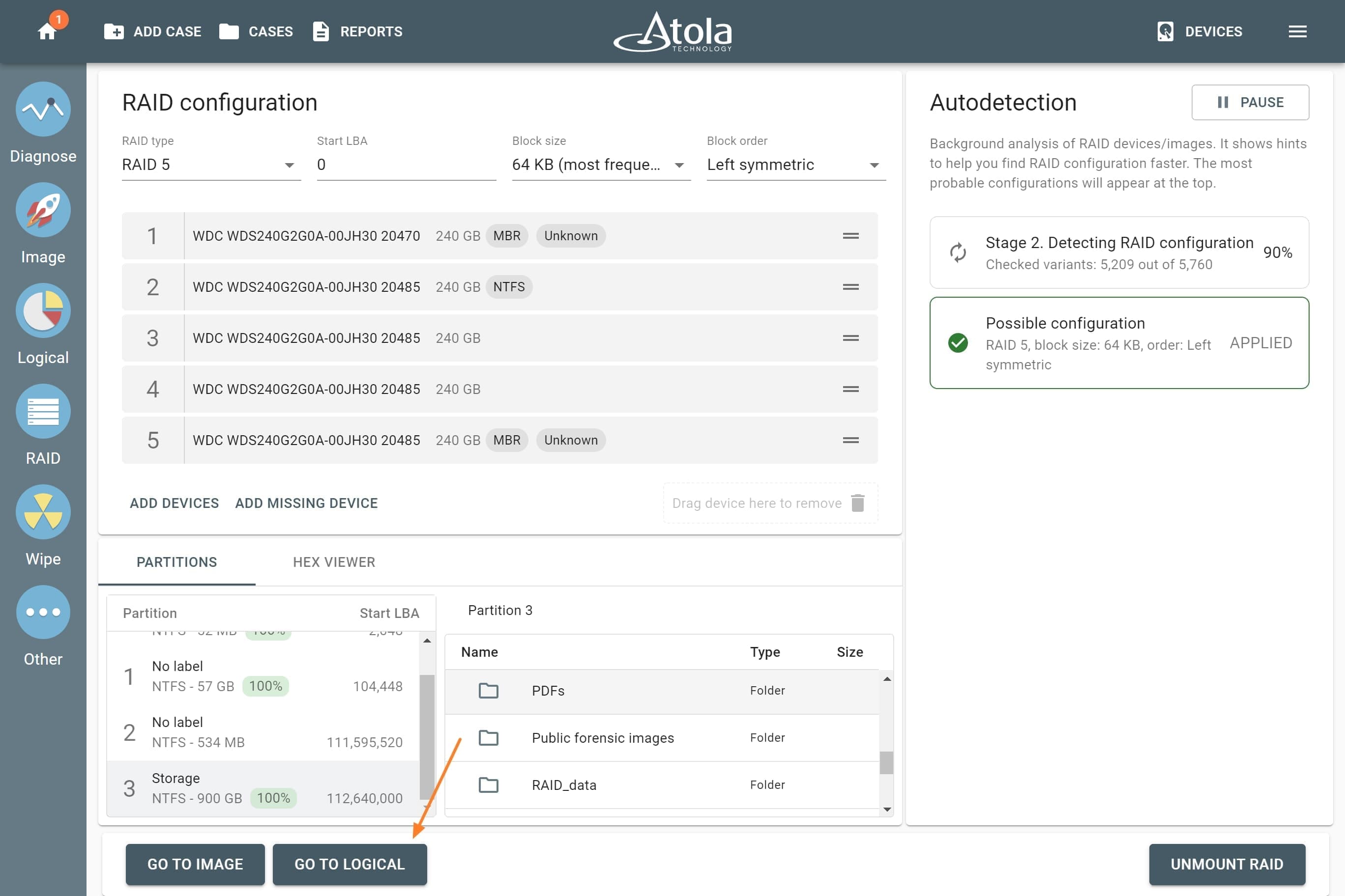
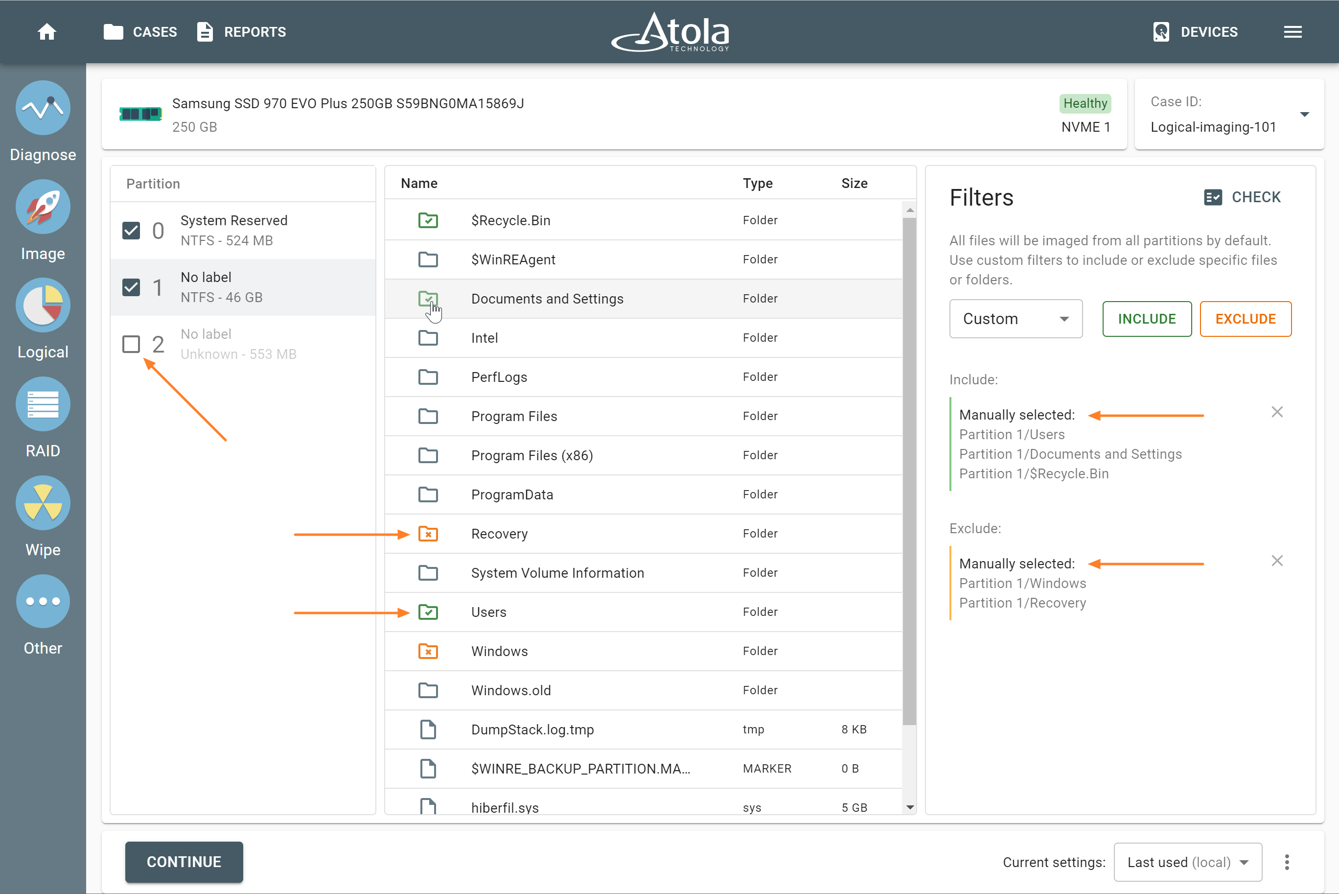
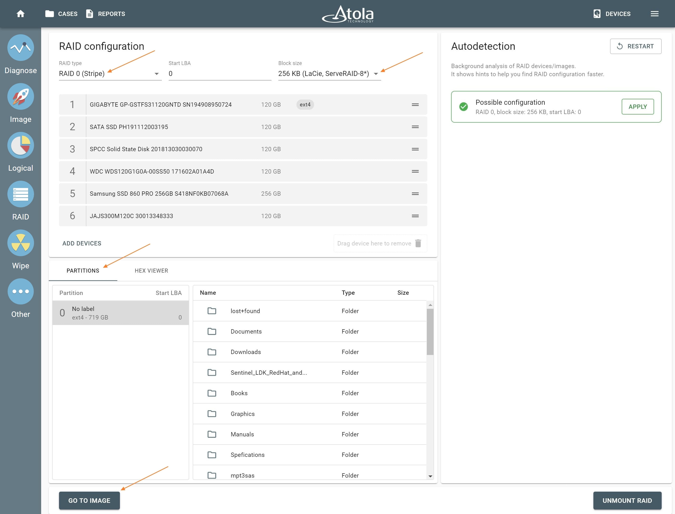
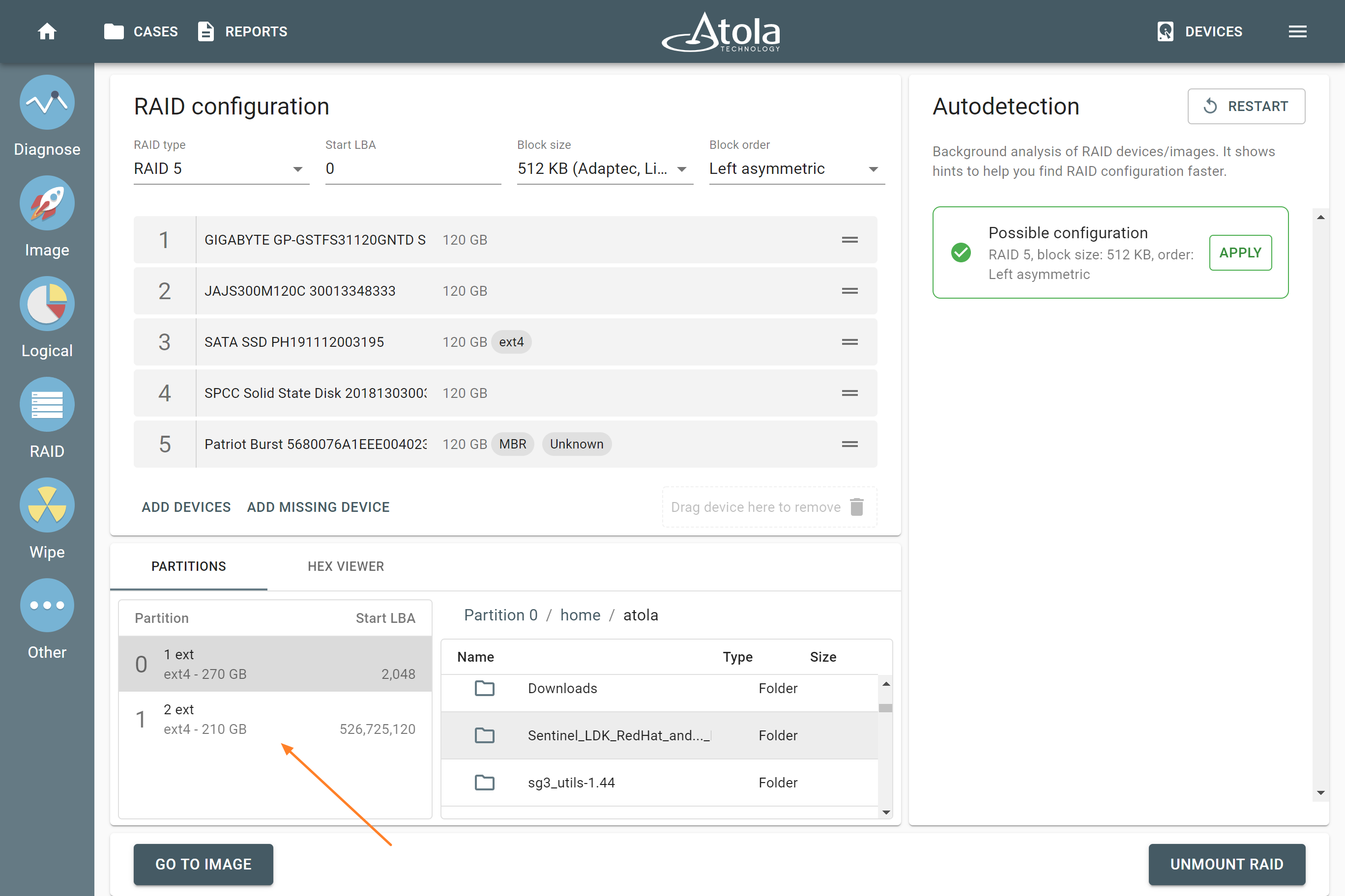
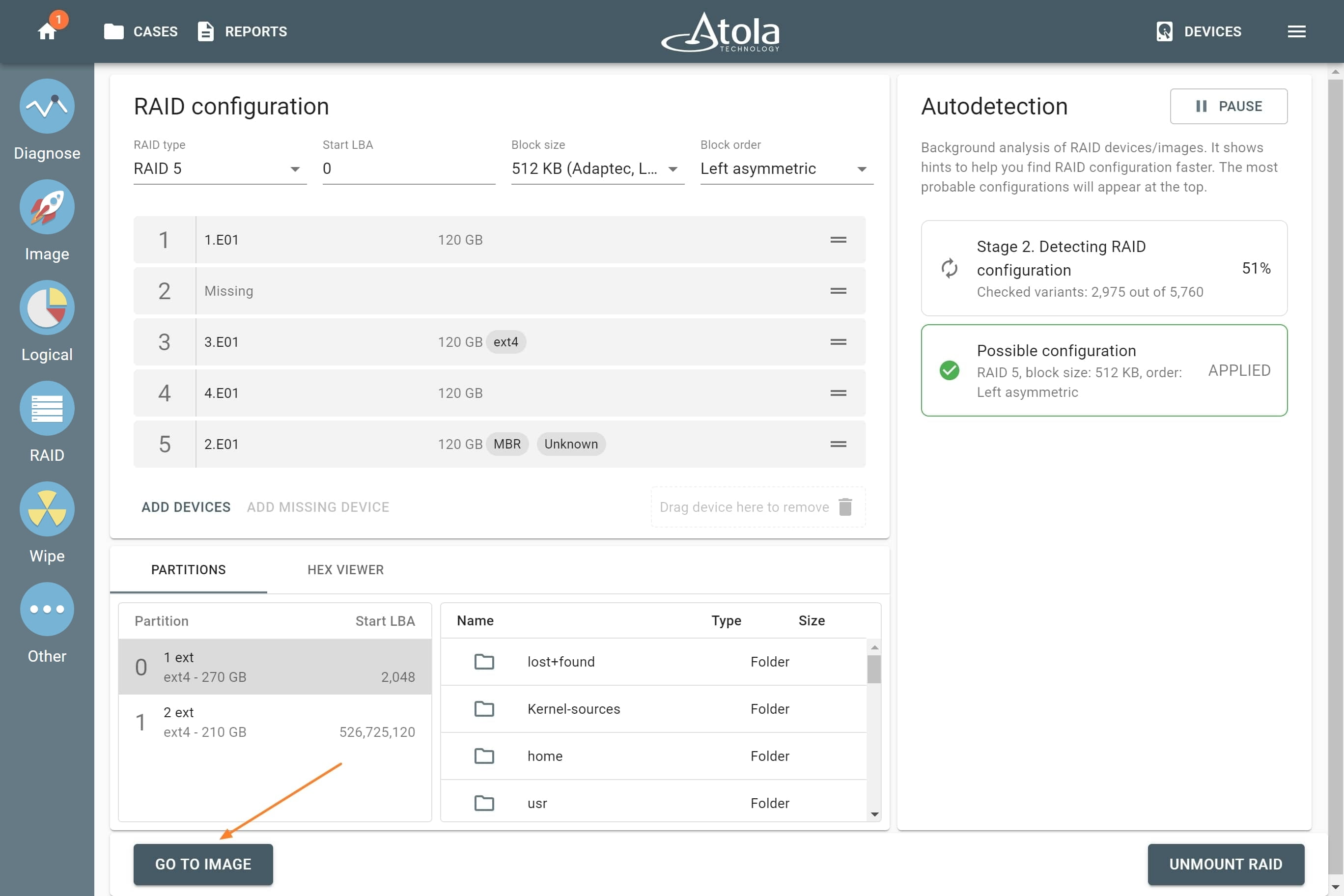
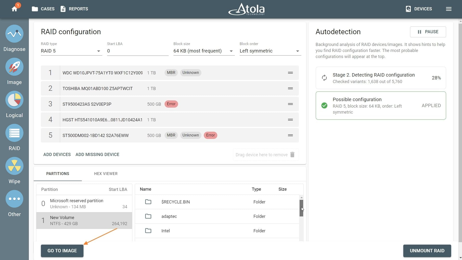
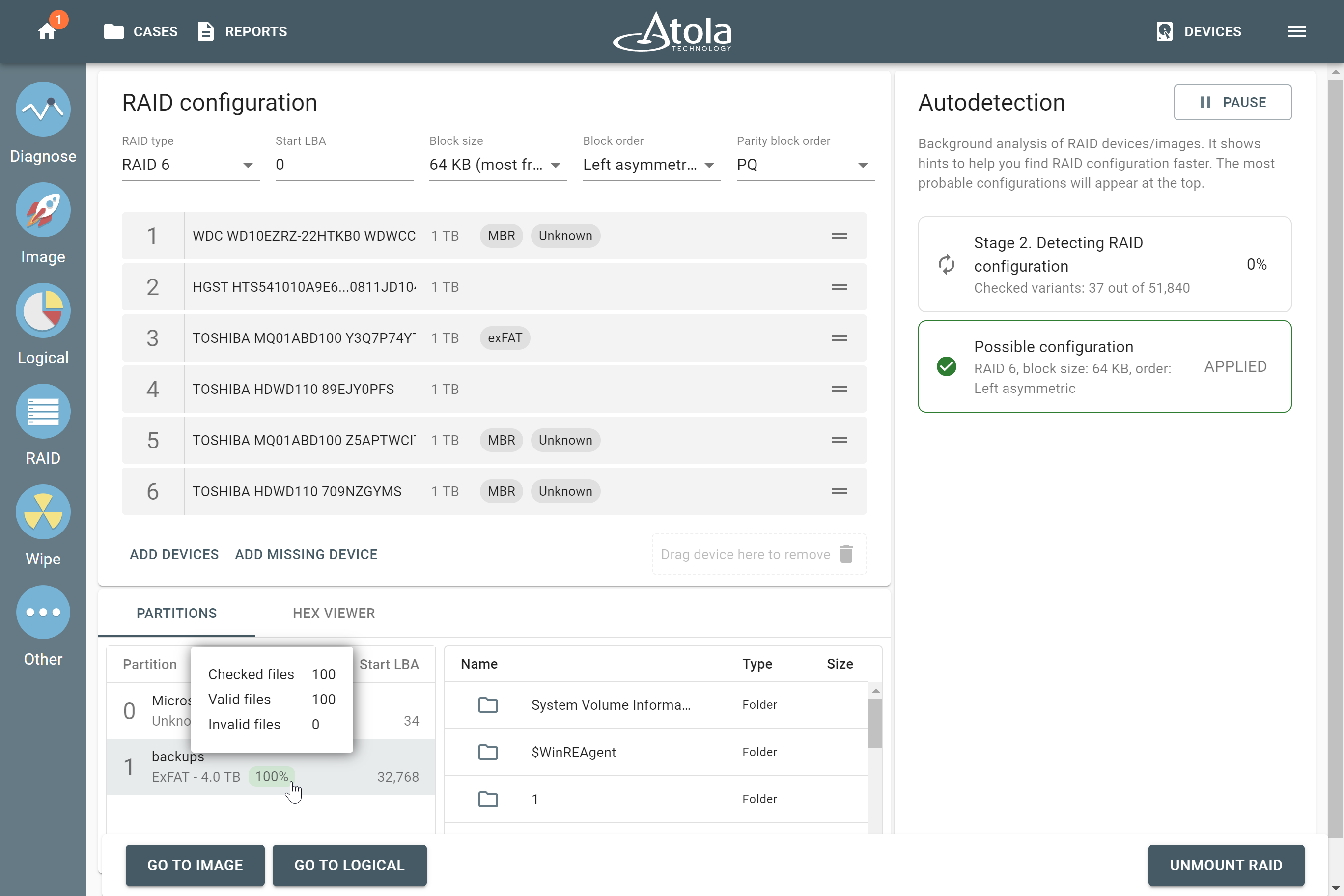
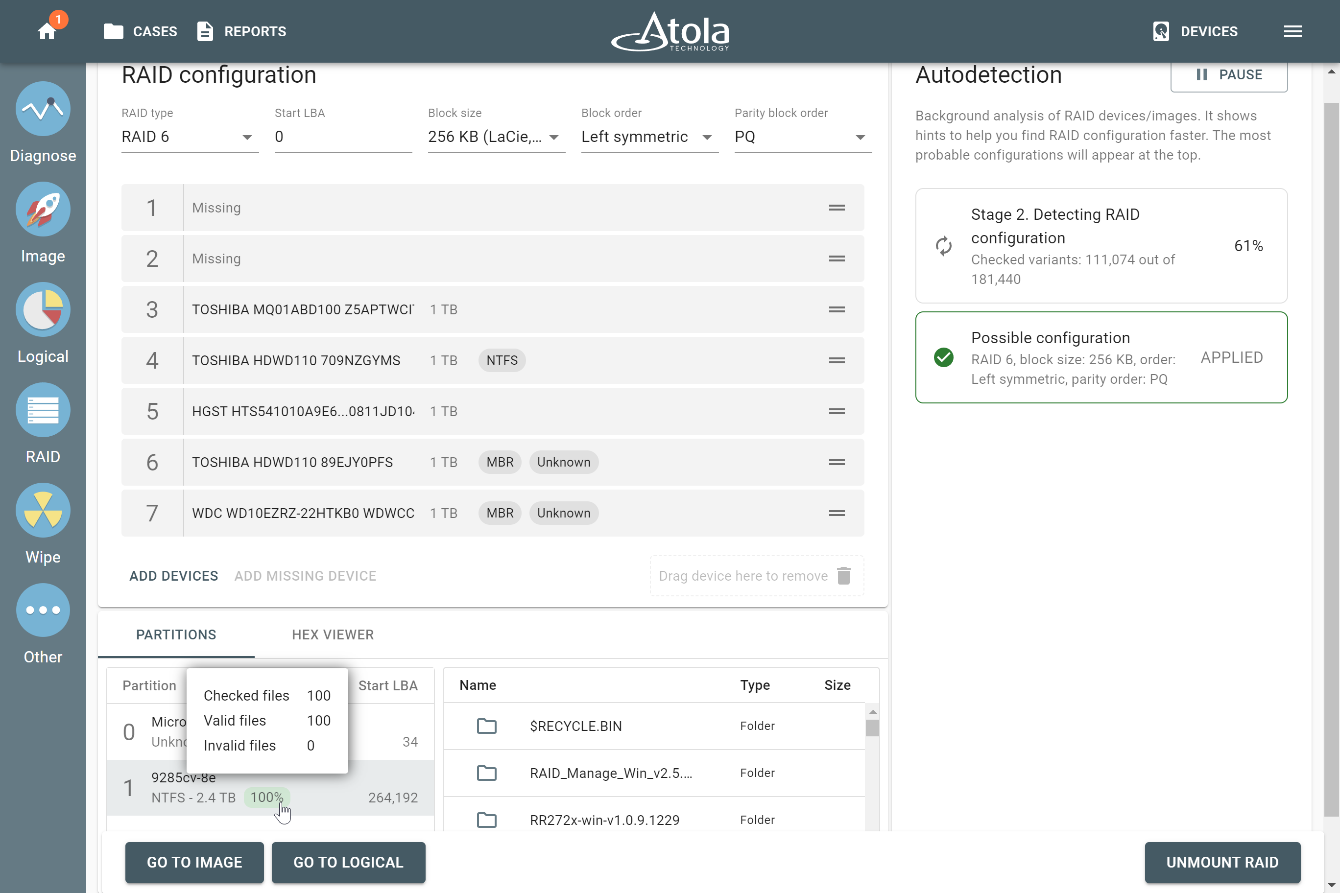
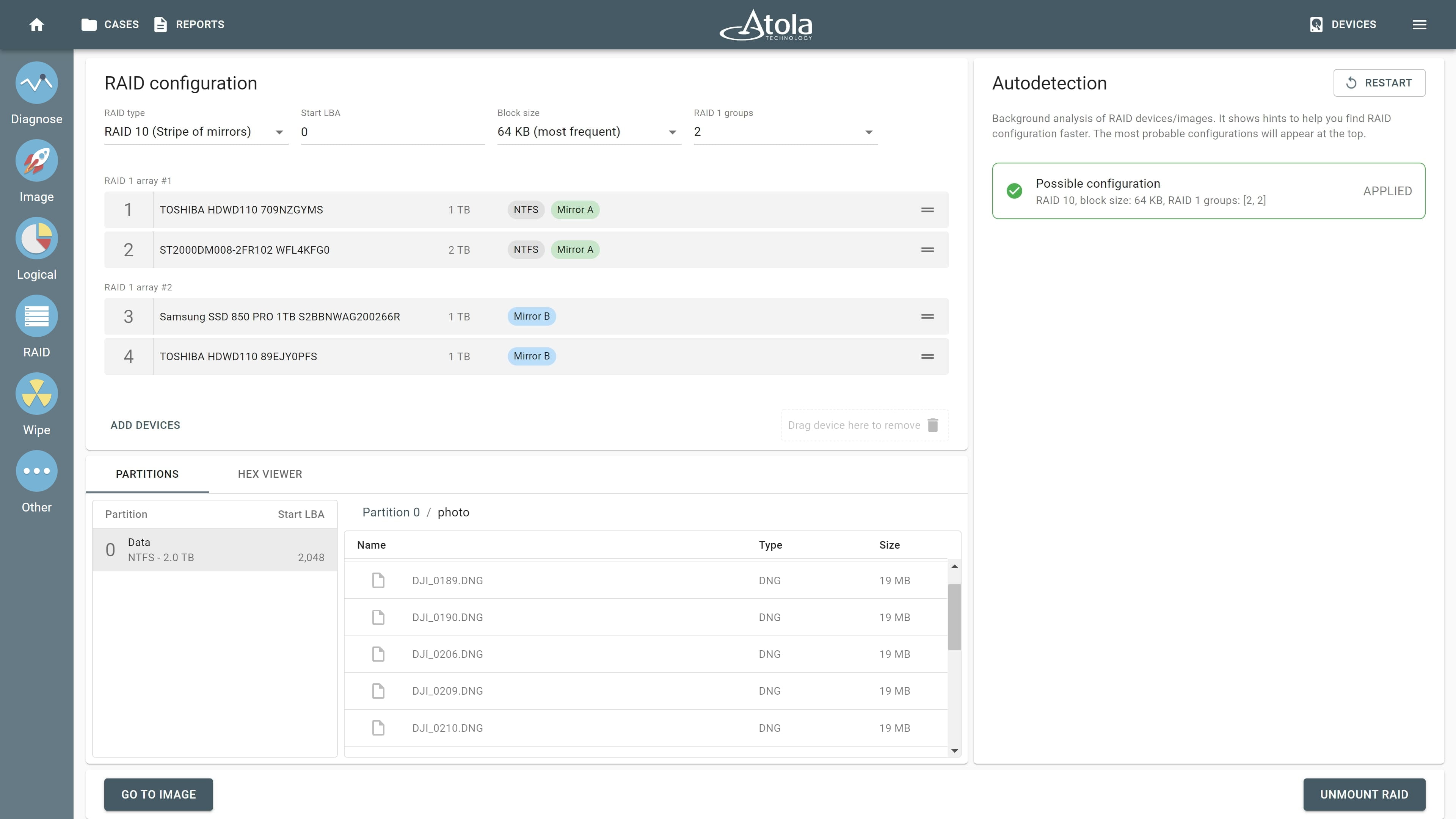
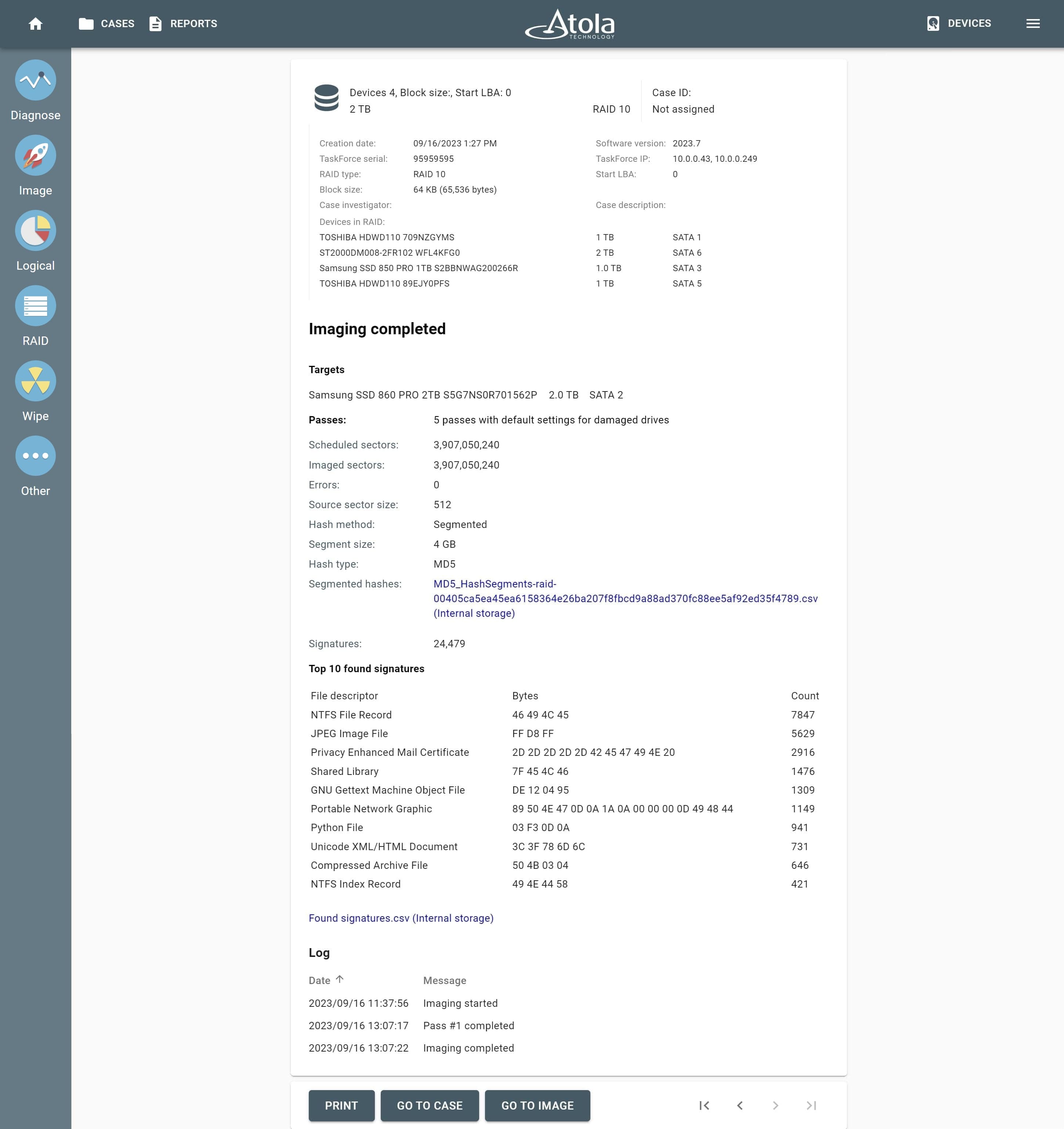
After reassembling RAID using other parameters, TaskForce automatically identifies its file system and shows a preview of its partitions, folders, and files.
Currently supported file systems are: .
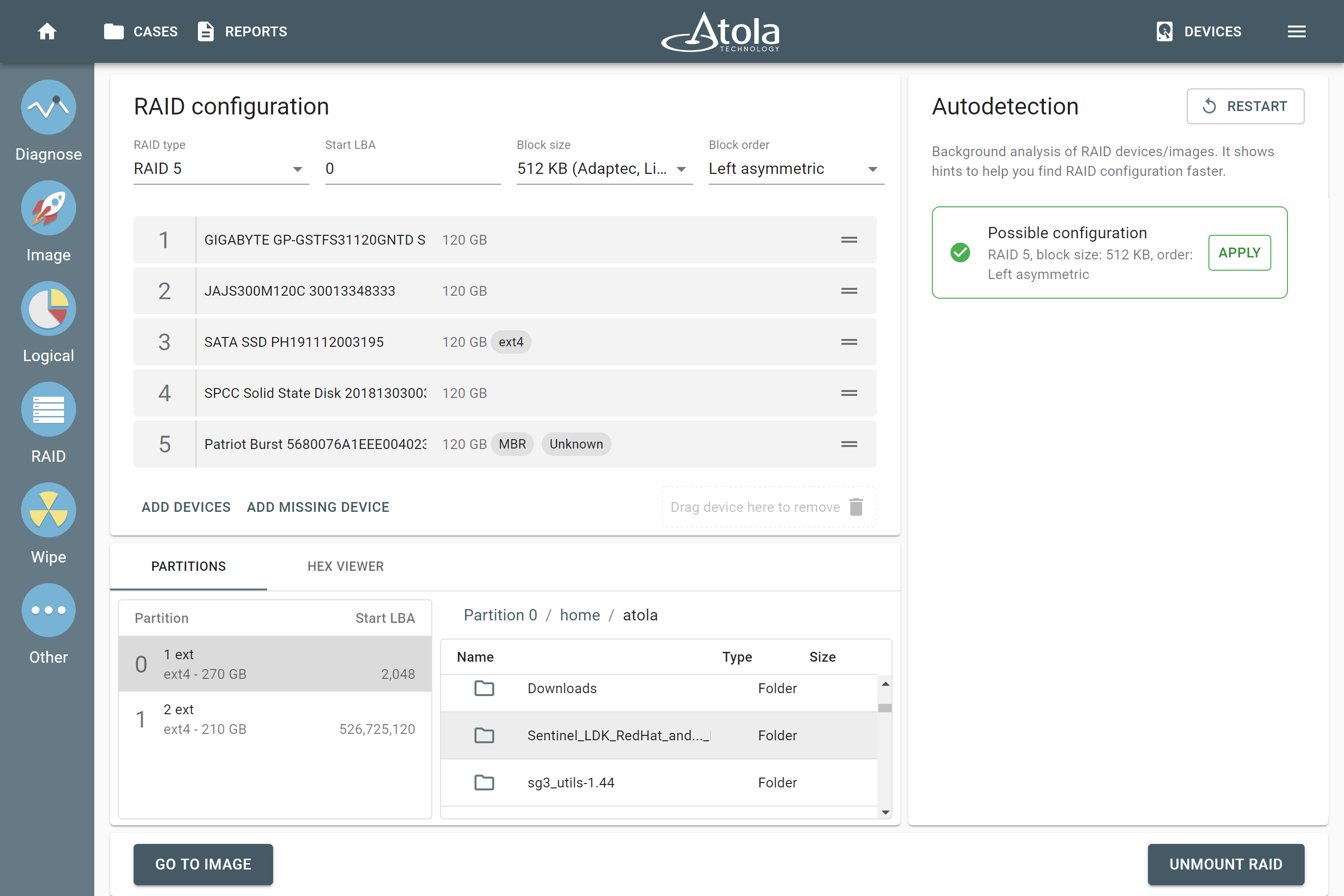
The preview of the RAID file system with partitions, folders, and files.
JBOD
JBOD is an abbreviation of "Just a Bunch Of Drives" and refers to a method for concatenation (or spanning) of multiple physical drives into a single logical disk with no redundancy. Data is written consecutively, from the beginning to the end of the first drive, and then spans to the second, the third and so on.
JBOD provides cost-effective storage with no performance or security benefits. It needs at least 2 drives to function. Array capacity is the sum of the capacities of its members.
If one drive fails, all data stored across the entire array may be compromised or lost, as JBOD does not implement any form of redundancy or fault tolerance.
JBOD advantages:
- Increasing capacity.
- Cost-effective storage.
JBOD disadvantages:
- No performance benefits.
- Redundancy is not provided.
JBOD parameters
When reassembling JBOD in Atola TaskForce, the following parameters are available for manual selection:
RAID 0 (Stripe)
In RAID 0, data is evenly distributed into stripes across two or more drives, forming a logical array, without parity or mirroring. RAID 0 provides higher reading and writing speed, as it can read and write multiple drives in parallel. As RAID 0 does not use mirroring or parity blocks, there’s no redundancy and fault tolerance: if one drive fails, data is lost.
RAID 0 needs at least 2 drives to function. Array volume is the sum of the capacities of the drives in the set, there’s no overhead provided by parity blocks.
RAID 0 advantages:
- Highest reading and writing speed.
- No overhead provided by parity blocks.
- Maximum capacity: sum of all RAID members.
RAID 0 disadvantages:
- No fault tolerance: if one drive fails, data is lost.
RAID 0 parameters
When reassembling RAID 0 in Atola TaskForce, the following parameters are available for manual selection:
RAID 1 (Mirror)
RAID 1 creates an exact copy of the drive's data (“mirror”) on another drive or drives. Thus RAID 1 usually consists of mirrored drives which are exact copies of each other. No spanning, striping, or parity is being used. The capacity of the array is limited to the size of the smallest member drive.
If one member drive fails, data is restored by copying from the mirror drive. Because of that RAID 1 can still work even if only one member drive is in good condition.
RAID 1 reads multiple drives in parallel, increasing overall reading performance. But writing speed is lower, as it takes additional time to duplicate data on the mirror drive.
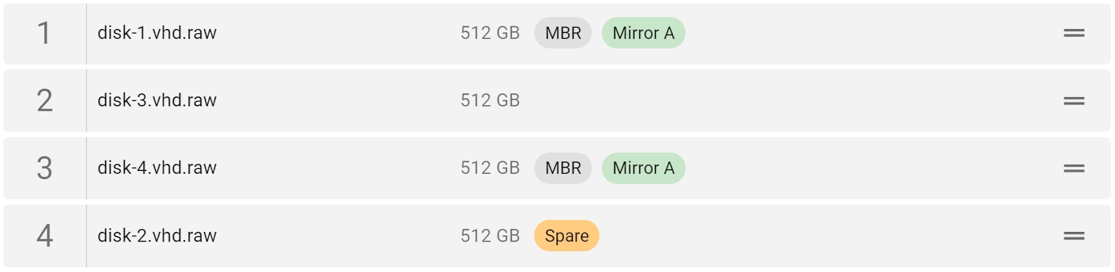
When TaskForce detects a mirrored pair of devices (drives or image files), it labels both of them with the “Mirror” tag.
RAID 1 advantages:
- Improved reading speed.
- High fault tolerance. Data can be restored from the “mirror” drive.
- Simplest RAID storage system.
RAID 1 disadvantages:
- Storage capacity is limited to the size of the smallest member drive.
- Writing speed is lower due to data duplication.
RAID 1 parameters
When reassembling RAID 1 in Atola TaskForce, the following parameters are available for manual selection:
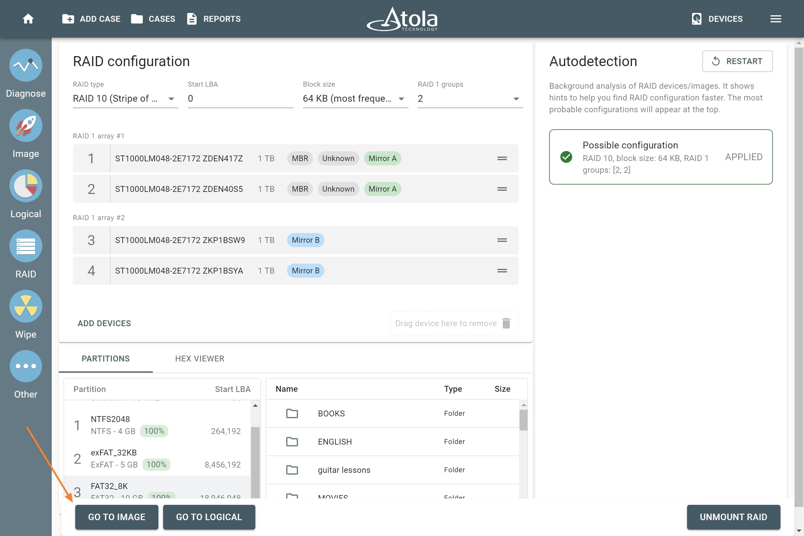
RAID 10 (Stripe of mirrors)
RAID 10 is called “stripe of mirrors” as it combines RAID 1 (“mirroring”) and RAID 0 (“striping”) methods within a single logical array. Data is shared between drives and duplicated. It is a RAID 0 array consisting of mirrors and thus requires a minimum of four drives: two for striping and two for storing mirrored data of each drive.
High read and write performance is achieved by striping RAID 1 mirrored segments.
If one member drive fails, data is restored by copying from the mirror drive. The overall storage capacity is reduced by 1/2 as all data is written twice.
RAID 10 typical use is highly loaded databases, email, or web servers.
When TaskForce detects a mirrored pair of devices (drives or image files), it labels both of them with the “Mirror” tag.
RAID 10 advantages:
- High reading and writing speed.
- High fault tolerance. Data can be restored from the “mirror” drive.
RAID 10 disadvantages:
- Storage capacity is reduced by 1/2 as all data is written twice.
- Limited scalability.
RAID 10 parameters
When reassembling RAID 10 in Atola TaskForce, the following parameters are available for manual selection:
RAID 5 (Distributed parity)
In RAID 5, data in the form of block-level stripes is evenly distributed across at least 3 drives, along with parity information which is used to restore data.
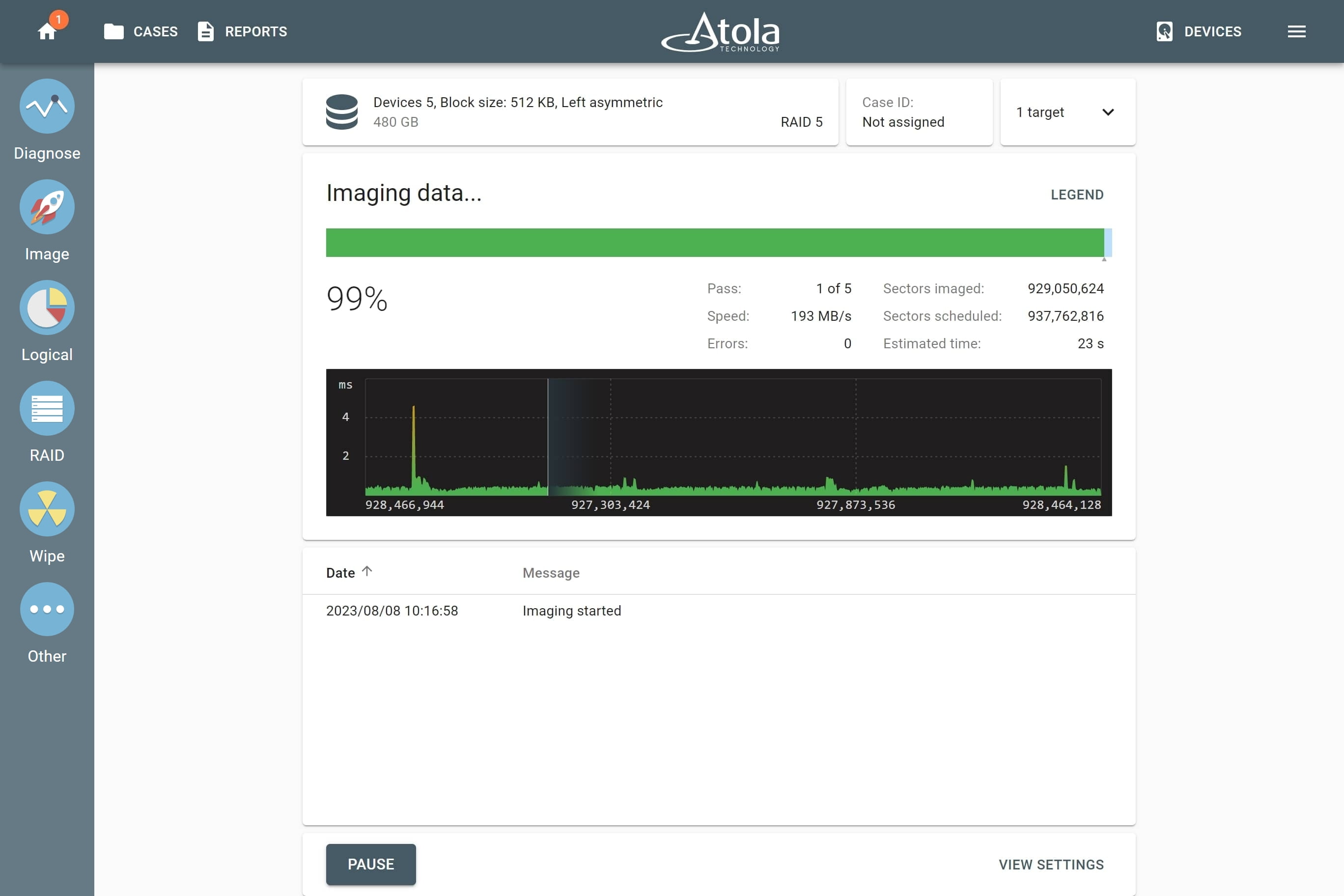
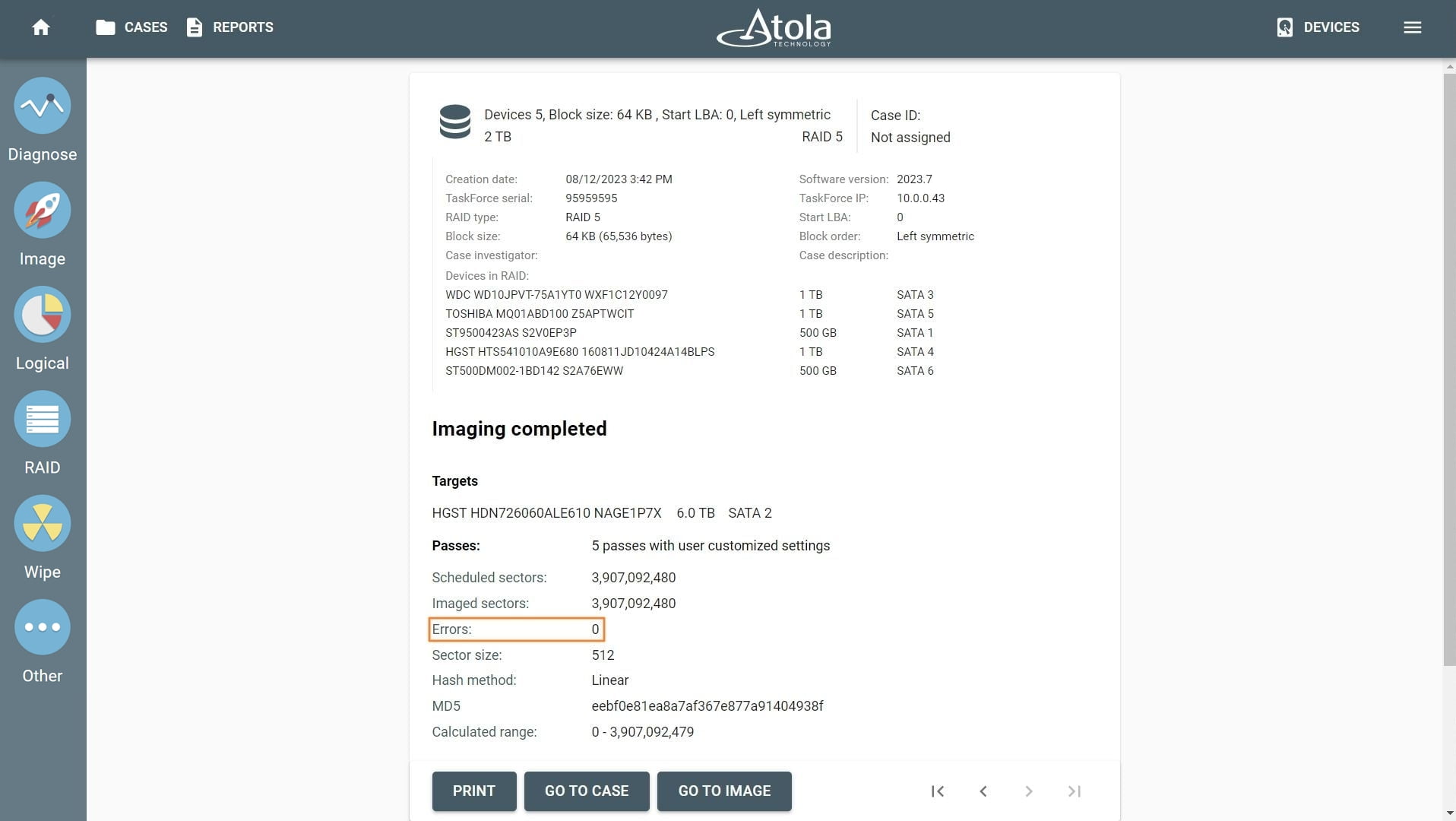
RAID 5 can still operate without one of its members. If one drive fails, its data is calculated from the parity blocks distributed across other members. Atola TaskForce can detect the parameters of the RAID 5 array with two damaged drives and successfully image such RAIDs regardless of errors.
The storage capacity of RAID 5 is reduced due to parity blocks.
Reading and writing speed is high since RAID 5 can read from and write to all array members in parallel.
RAID 5 is typically used for file servers, database servers, and application servers.
RAID 5 can have different layouts, or block orders, depending on the pattern in which RAID 5 data blocks (“stripes”) and parity blocks are distributed among the devices in the array. The layout is defined by:
- The direction of data blocks writing: left to right or right to left on the disk array.
- The placement of the parity blocks: at the beginning or end of a stripe.
- The location of the first block of a stripe relative to the parity of the previous stripe.
There are four RAID 5 layouts (or block orders):
- Left symmetric.
- Right symmetric.
- Left asymmetric.
- Right asymmetric.
RAID 5 advantages:
-
High read speed but slightly lower than RAID 0 because of the overhead from parity calculations and distribution across all disks.
-
High fault tolerance. Data from one failed drive can be restored using parity information, stored on other array members.
RAID 5 disadvantages:
-
Storage capacity is reduced due to parity blocks. Space efficiency is described by formula: 1 − 1/n, where n is the number of devices in an array. For instance, for RAID 5 consisting of 5 drives with total capacity of 1 TB, available space will be reduced by 1/5 (or 200 MB), to 800 MB.
-
Moderate write speed due to the need for parity calculations and writing both data and parity information.
RAID 5 parameters
When reassembling RAID 5 in Atola TaskForce, the following parameters are available for manual selection:
RAID 6 (Dual parity)
RAID 6 uses block-level striping (data is shared between drives) with two parity blocks, instead of one, distributed across all member disks. This gives extra redundancy to an array: RAID 6 can read and write data even if two drives fail at the same time.
This RAID type needs at least 4 drives to function. Storage capacity is reduced because of the dual parity scheme.
RAID 6 is typically used for large file storage, file servers, database servers, app servers.
Thanks to RAID 6 extra redundancy coming from two parity block types, TaskForce can rebuild a RAID 6 array even if two of its members are missing or damaged.
RAID 6 can have different layouts, or block orders, depending on the pattern in which RAID 6 data blocks (“stripes”) and parity blocks are distributed among the devices in the array. The layout is defined by:
- The direction of data blocks writing: left to right or right to left on the disk array.
- The placement of the parity blocks: at the beginning or end of the stripe.
- Parity block order.
- The location of the first block of a stripe relative to the parity of the previous stripe.
RAID 6 advantages:
- Very high data fault tolerance.
- Data can be restored even if two drives fail.
- High reading speed similar to RAID 5, but can be slightly slower due to additional parity calculations.
RAID 6 disadvantages:
- Storage capacity is reduced because of the dual parity scheme.
- Reduced writing speed due to the usage of two types of parity blocks.
- Minimum 4 drives needed.
RAID 6 parameters
When reassembling RAID 6 in Atola TaskForce, the following parameters are available for manual selection:
RAID read and write speeds
The different RAID levels offer various trade-offs in terms of read and write speed, redundancy, and storage efficiency. Below is a comparison of RAID 0, 1, 10, 5, and 6 regarding their read and write speeds.
| RAID type |
Read Speed |
Write Speed |
| RAID 0 |
Highest because data is striped across all disks, allowing simultaneous reads.
|
Highest because data is striped, allowing simultaneous writes. No parity calculation delay.
|
| RAID 1 |
High because data can be read from either of the mirrored disks, potentially doubling the read rate compared to a single disk.
|
Lower than RAID 0 because all data must be written to two disks, causing a slight overhead.
|
| RAID 10 |
High, similar to RAID 1 because it combines striping and mirroring, offering improved read rates through simultaneous disk reads.
|
Moderate to High because data is mirrored across pairs, but the striping allows for higher write speeds compared to just RAID 1.
|
| RAID 5 |
High but slightly lower than RAID 0 because of the overhead from parity calculations and distribution across all disks.
|
Moderate due to the need for parity calculations and writing both data and parity information, which introduces some overhead.
|
| RAID 6 |
High, similar to RAID 5, but can be slightly slower due to additional parity calculations.
|
Lower than RAID 5 because it requires two parity blocks to be written, further increasing the overhead compared to RAID 5.
|
Key Points:
-
RAID 0 offers the best performance both in reads and writes but no redundancy.
-
RAID 1 provides good read performance and redundancy at the cost of available capacity.
-
RAID 10 combines the benefits of RAID 0 and RAID 1, offering a good balance of speed and redundancy.
-
RAID 5 and RAID 6 offer a good balance between storage efficiency, read speed, and redundancy, with RAID 6 providing higher fault tolerance at the cost of write speed due to additional parity calculations.