Quickstart
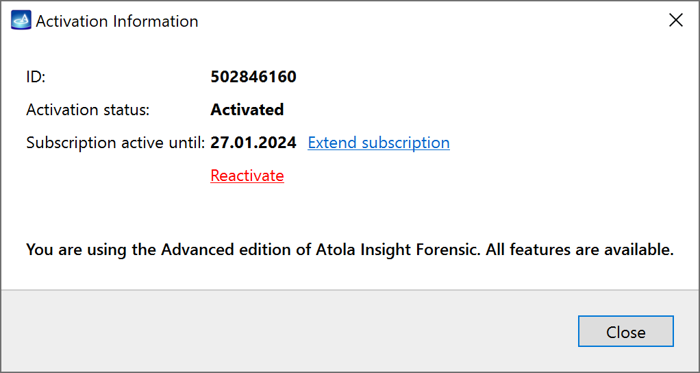
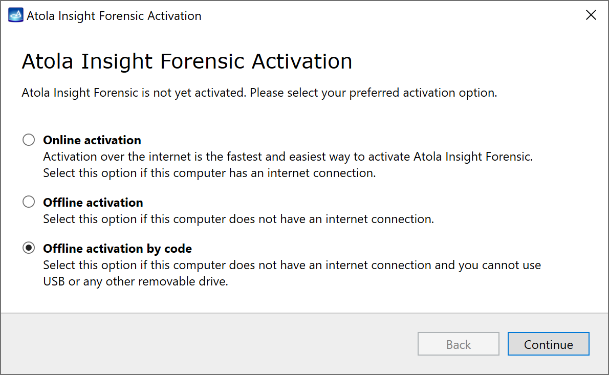
Assuming you have Atola Insight Forensic software installed and activated, let us start from zero and learn how to image an evidence device safely in Atola Insight Forensic.
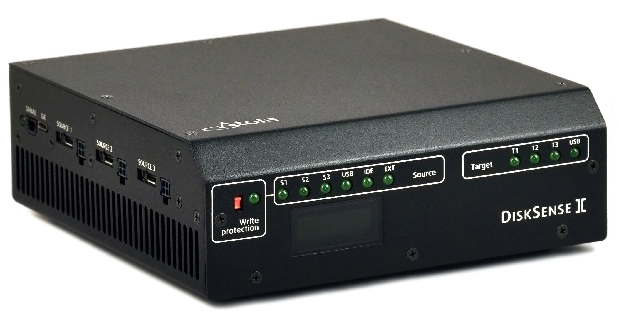
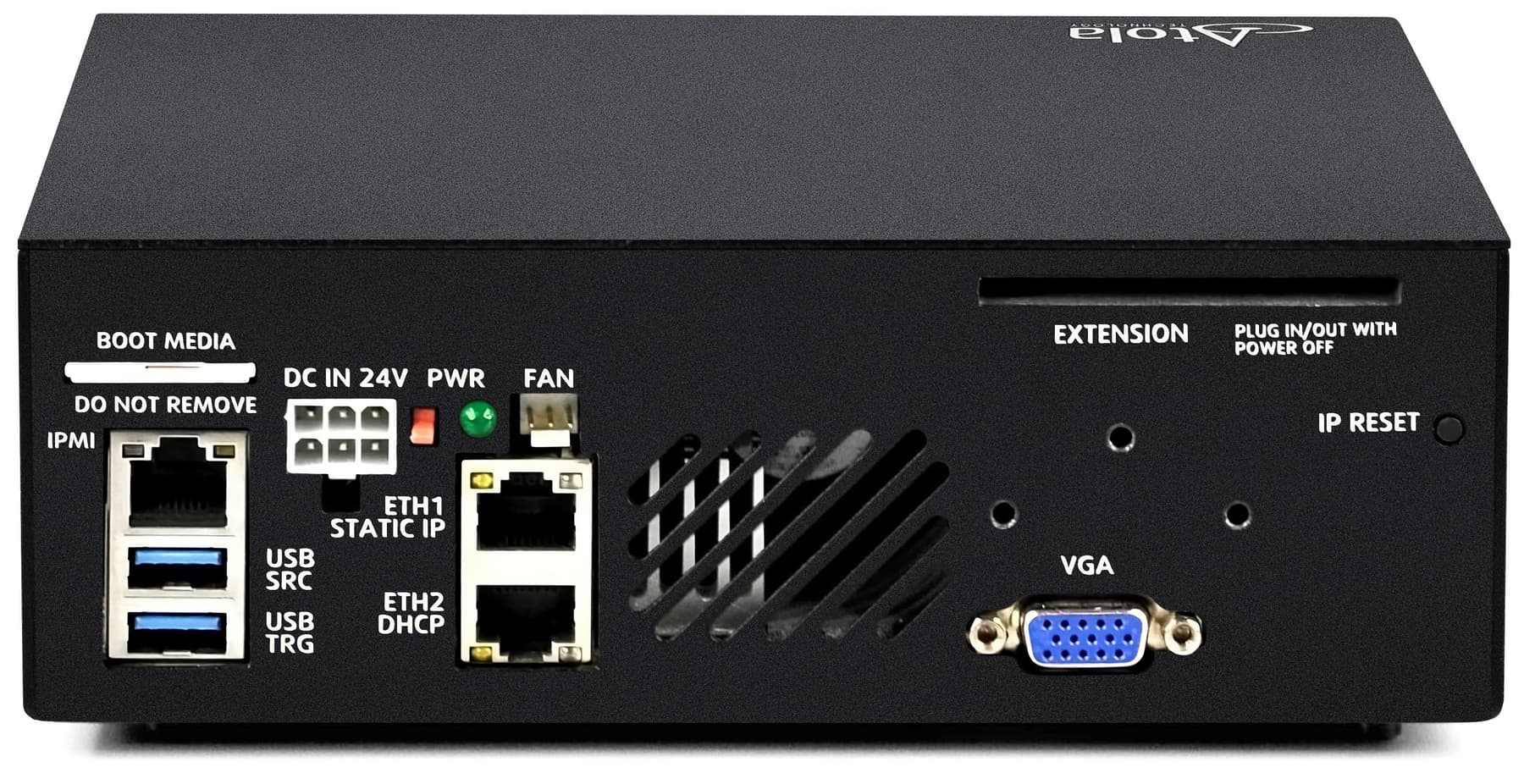
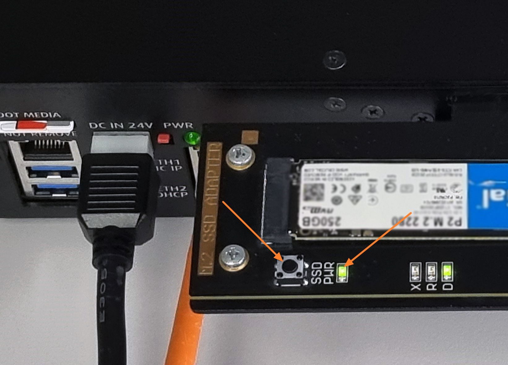
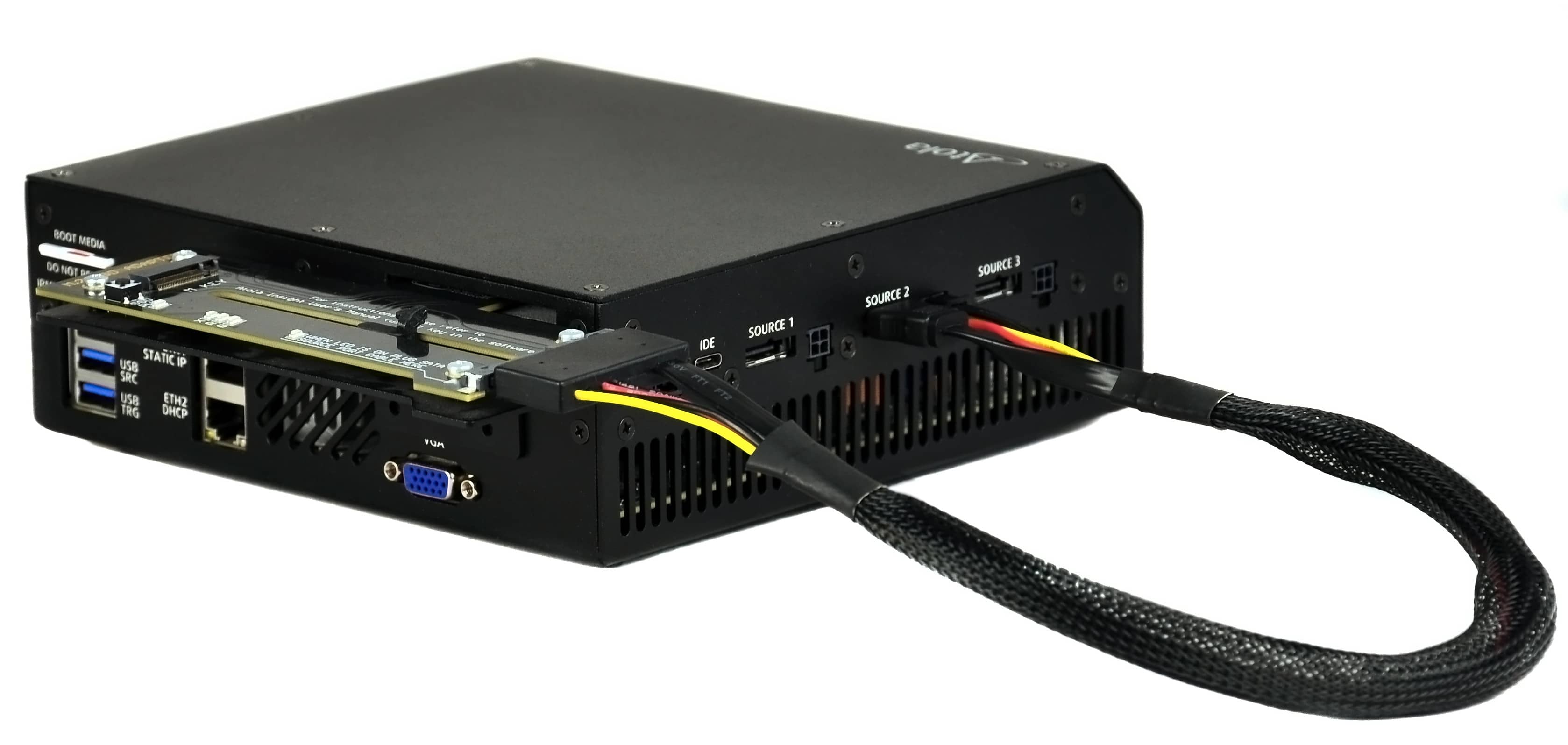
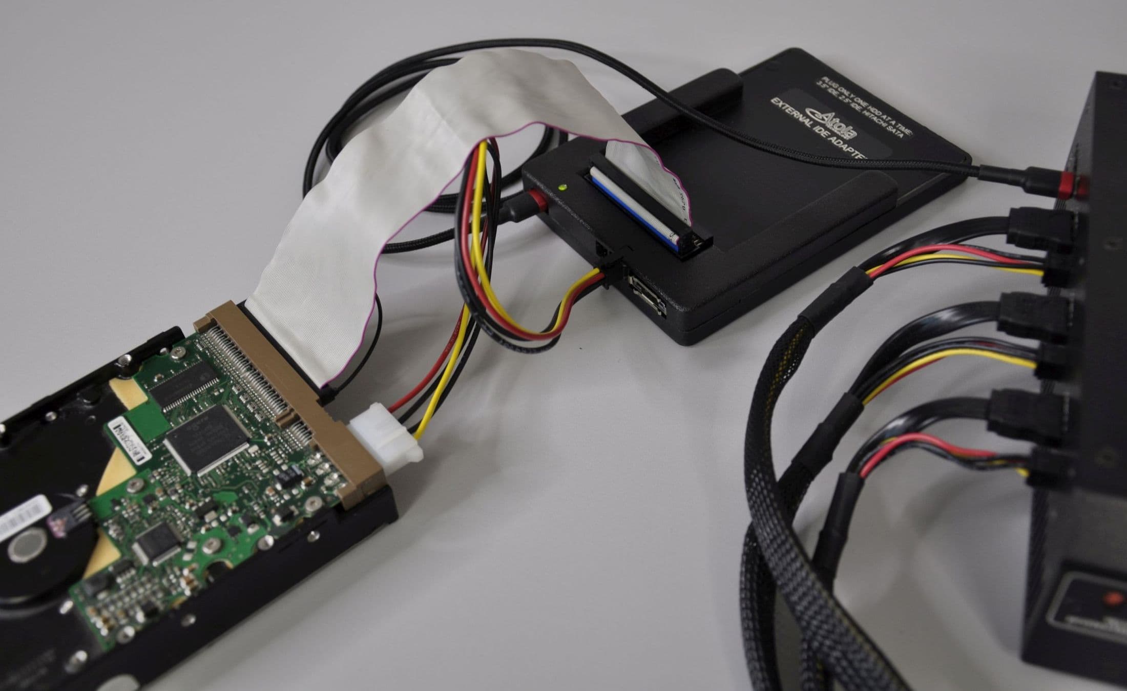
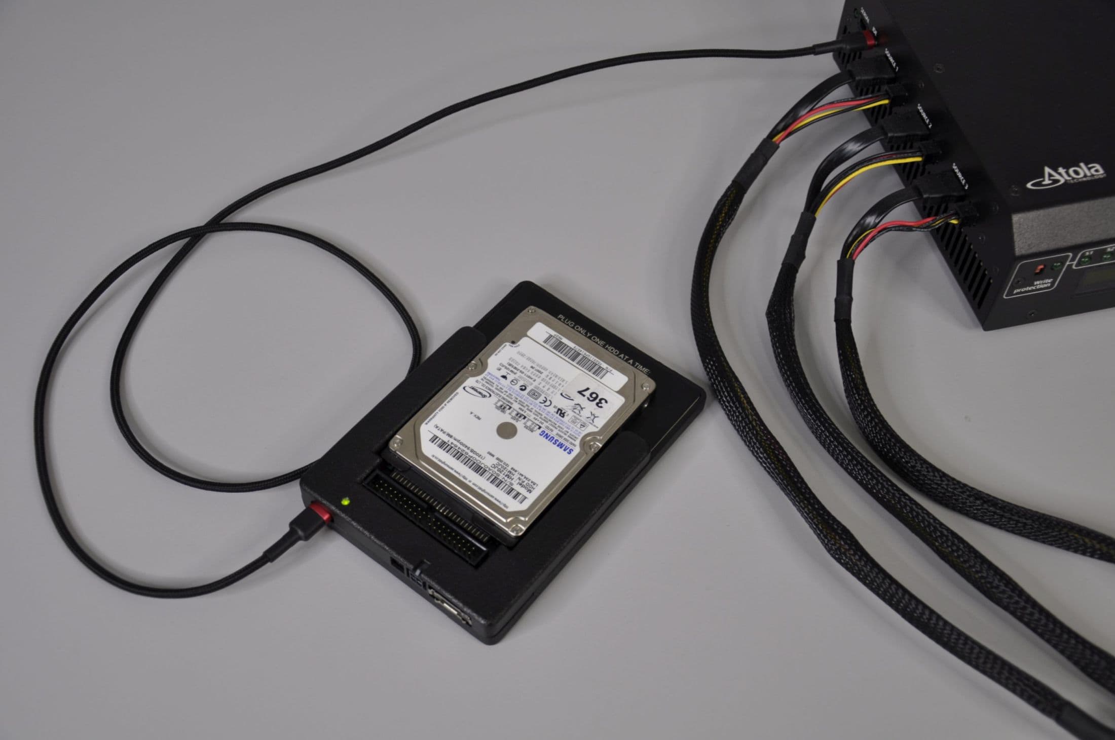
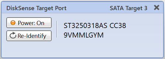
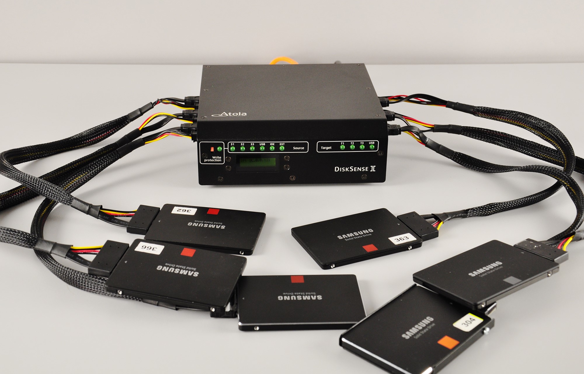
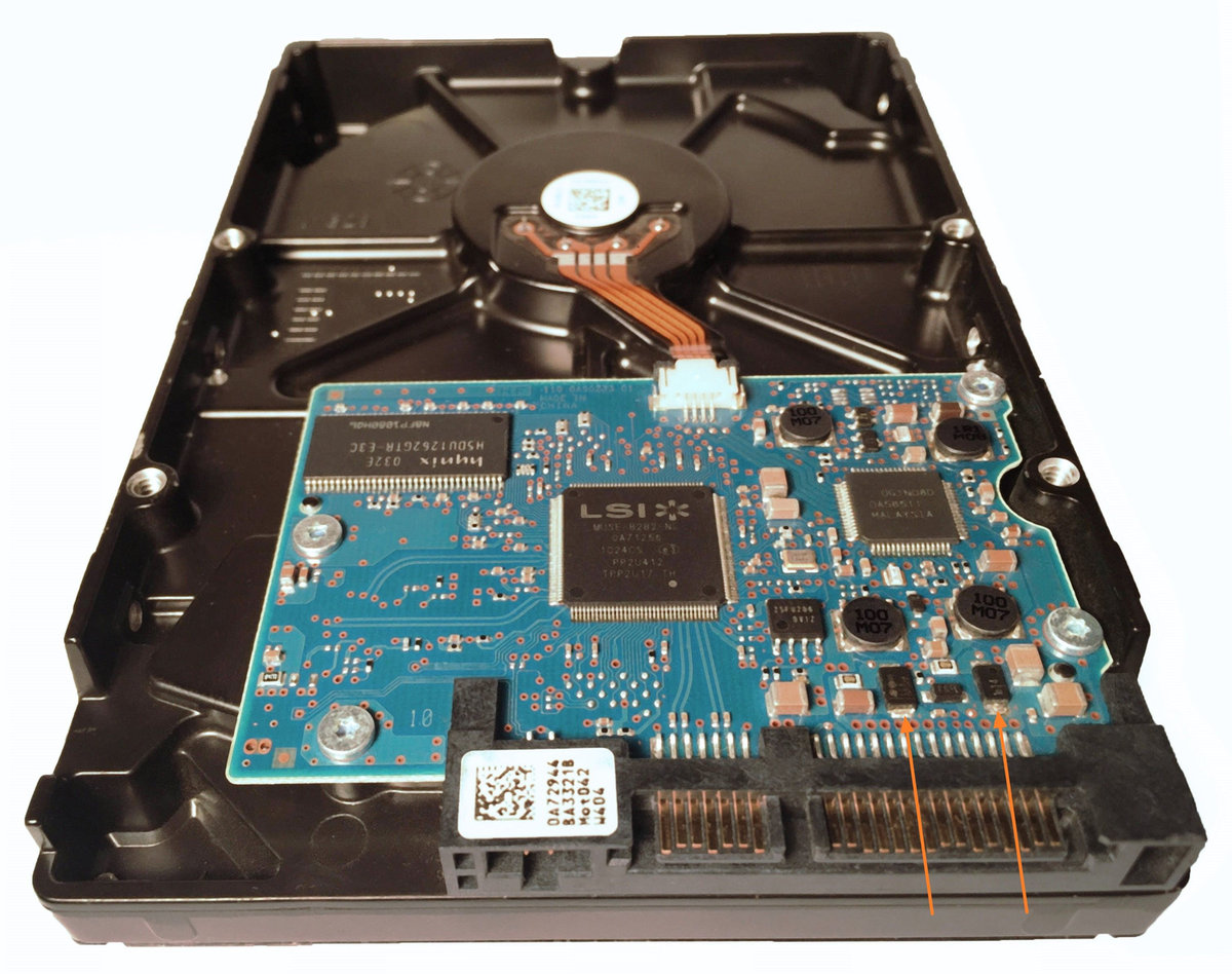
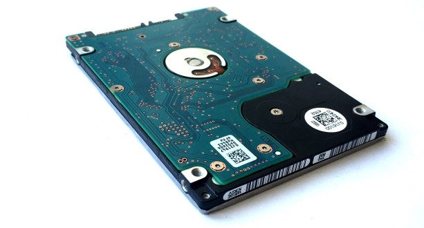
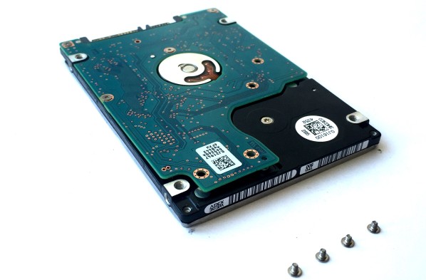
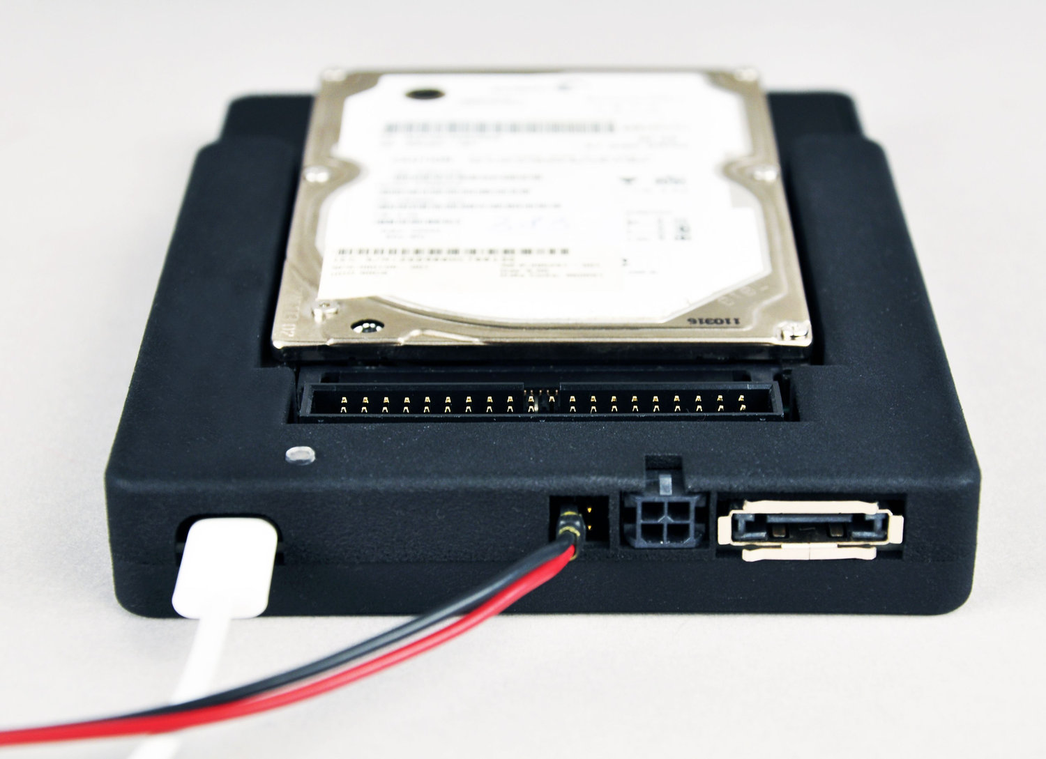
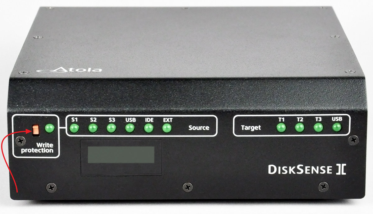
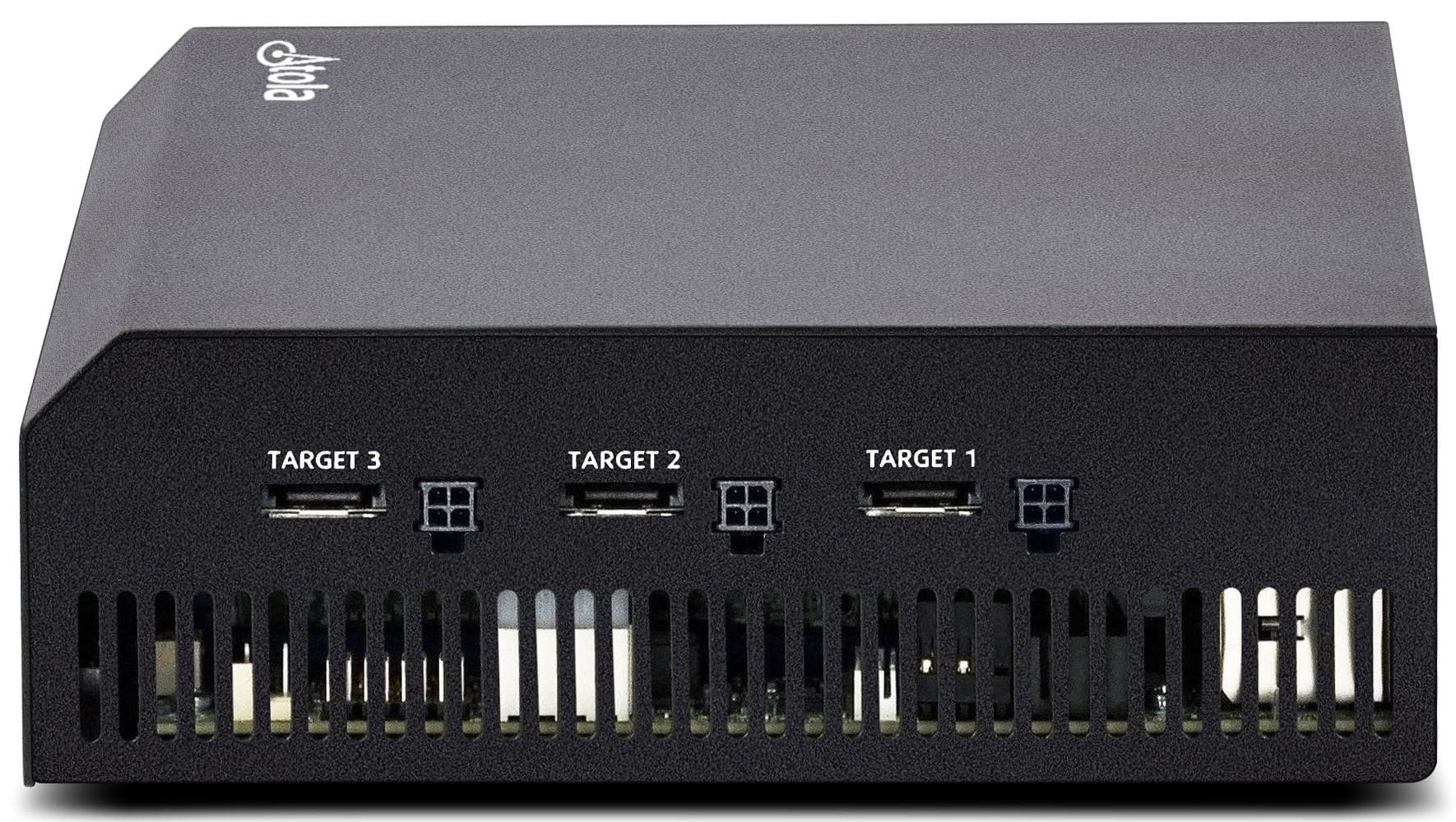
Step 1. Plug the source and target devices into the DiskSense 2 hardware unit.
Take two SATA drives that will serve as your source and target devices. Plug them into the SATA source and SATA target ports.

Step 2. Launch Atola Insight.
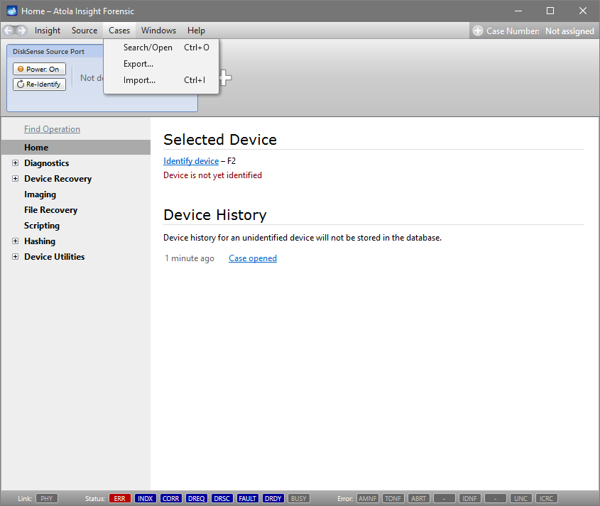
Launch already installed Atola Insight Forensic software.
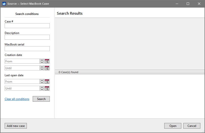
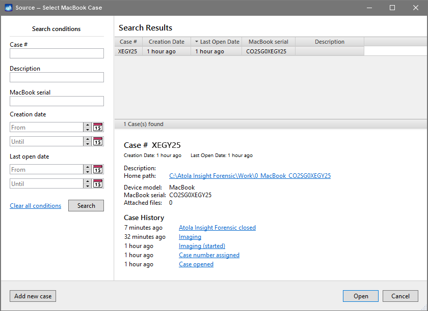
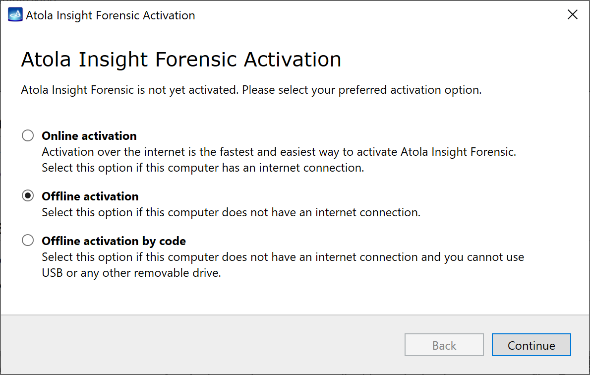
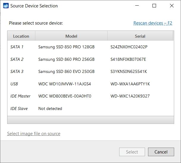
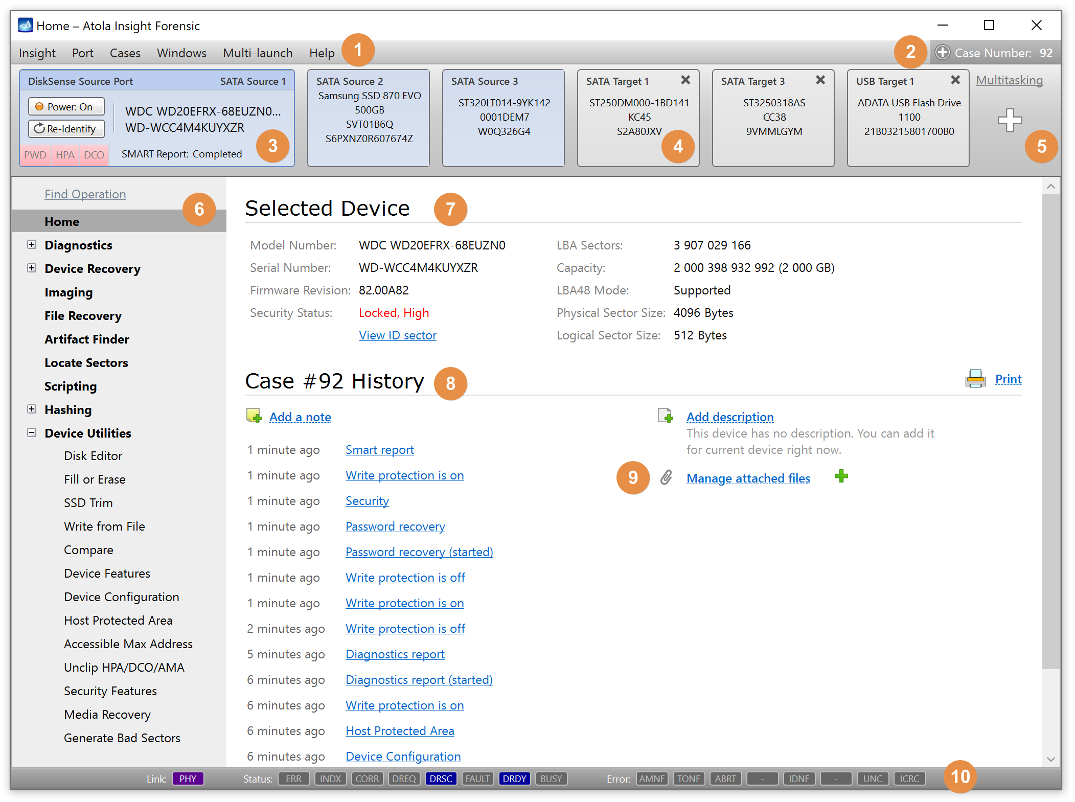
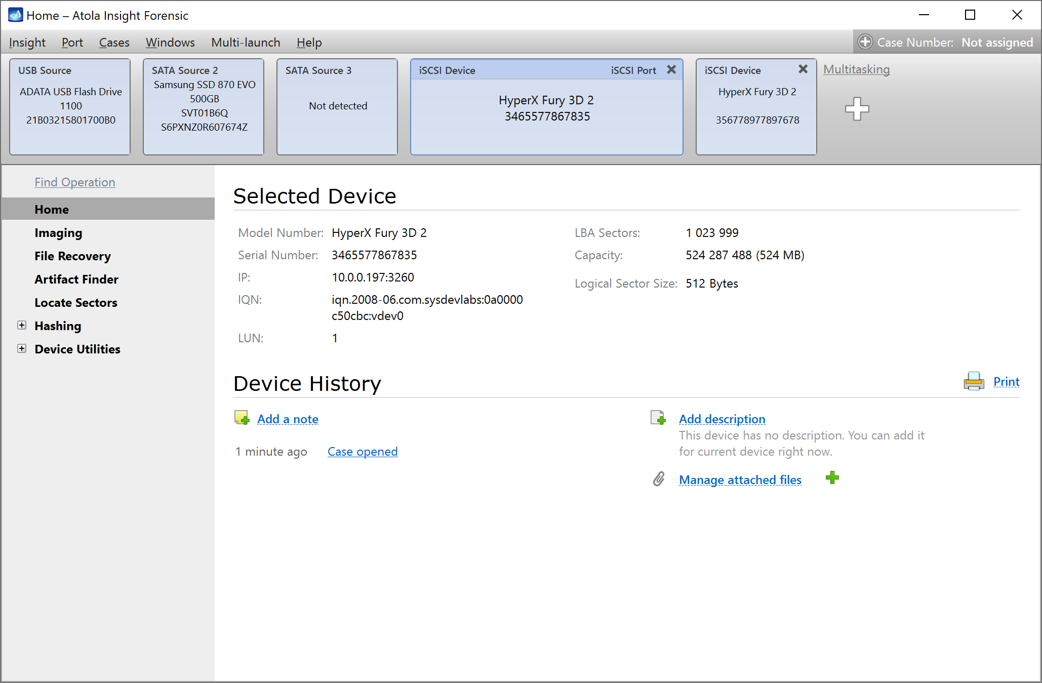
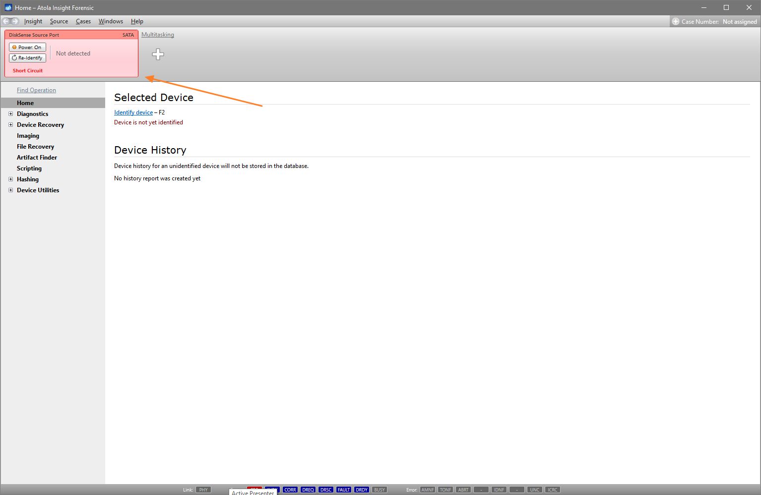
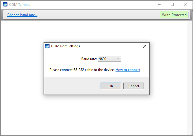
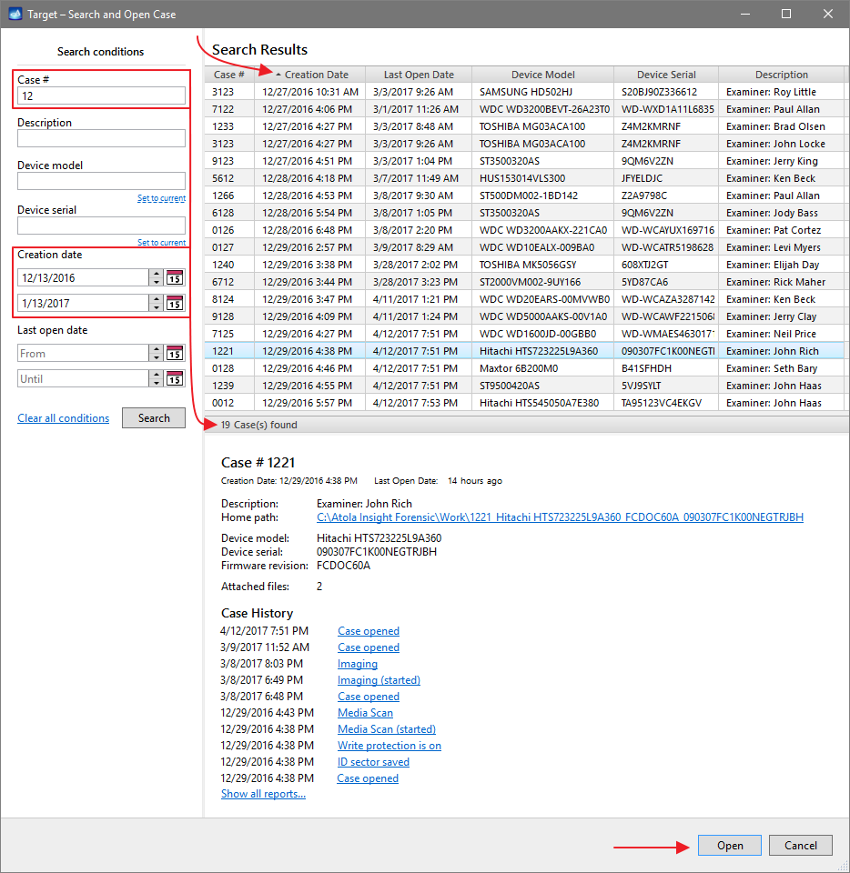
You will see the following window requesting that you select the desired action:
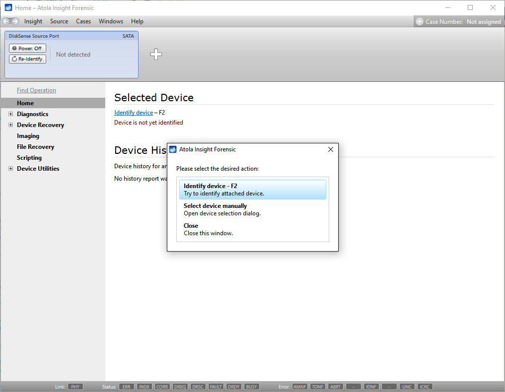
Select Close to avoid powering up the source SATA port for now.
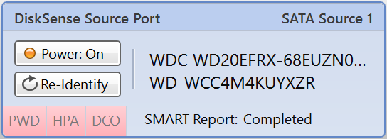
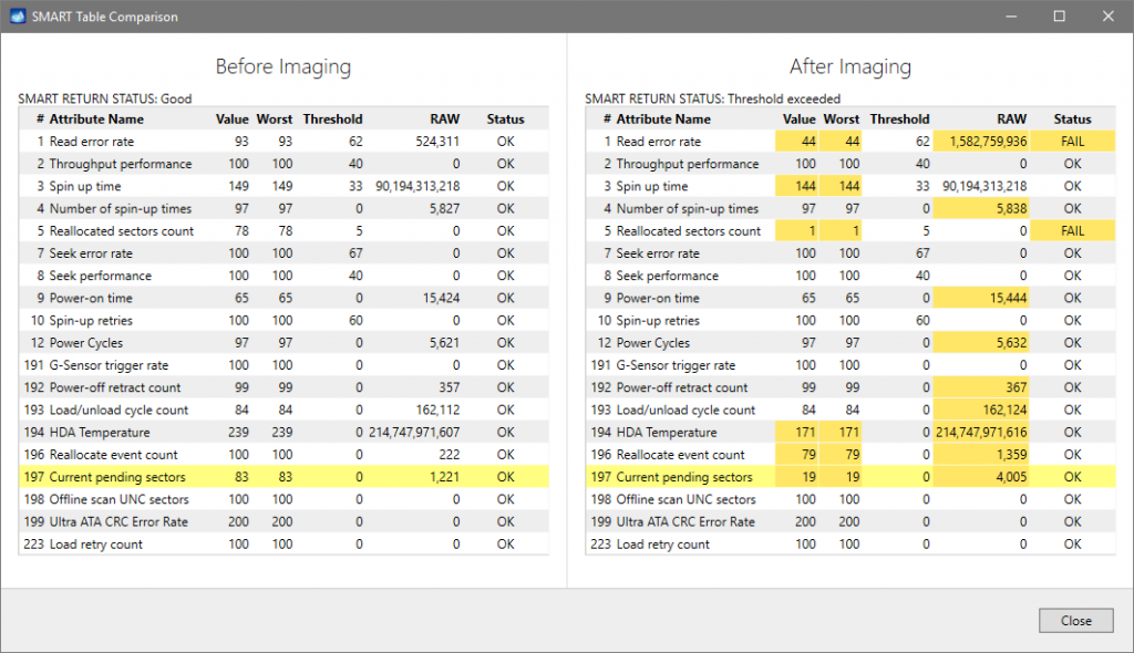
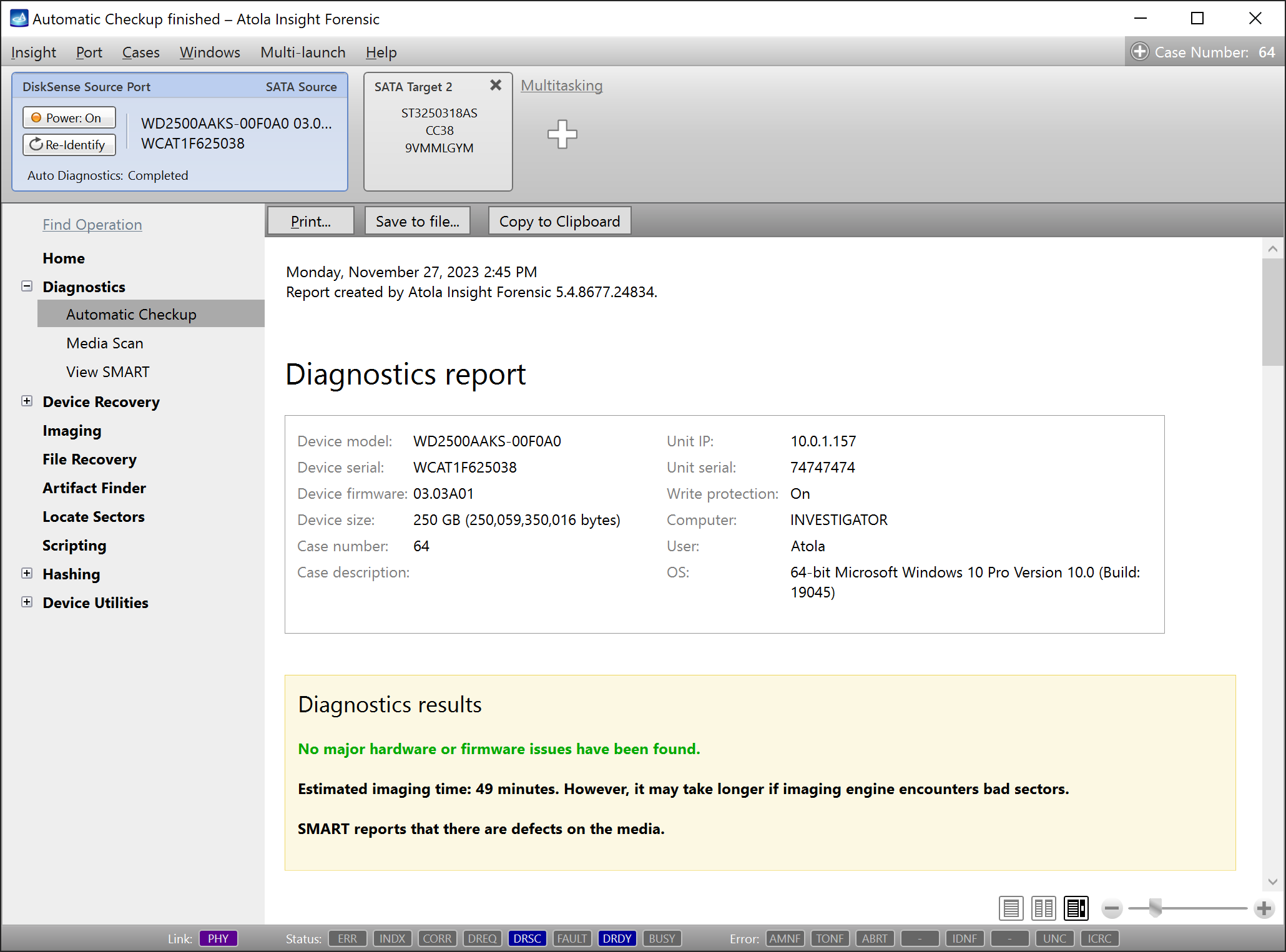
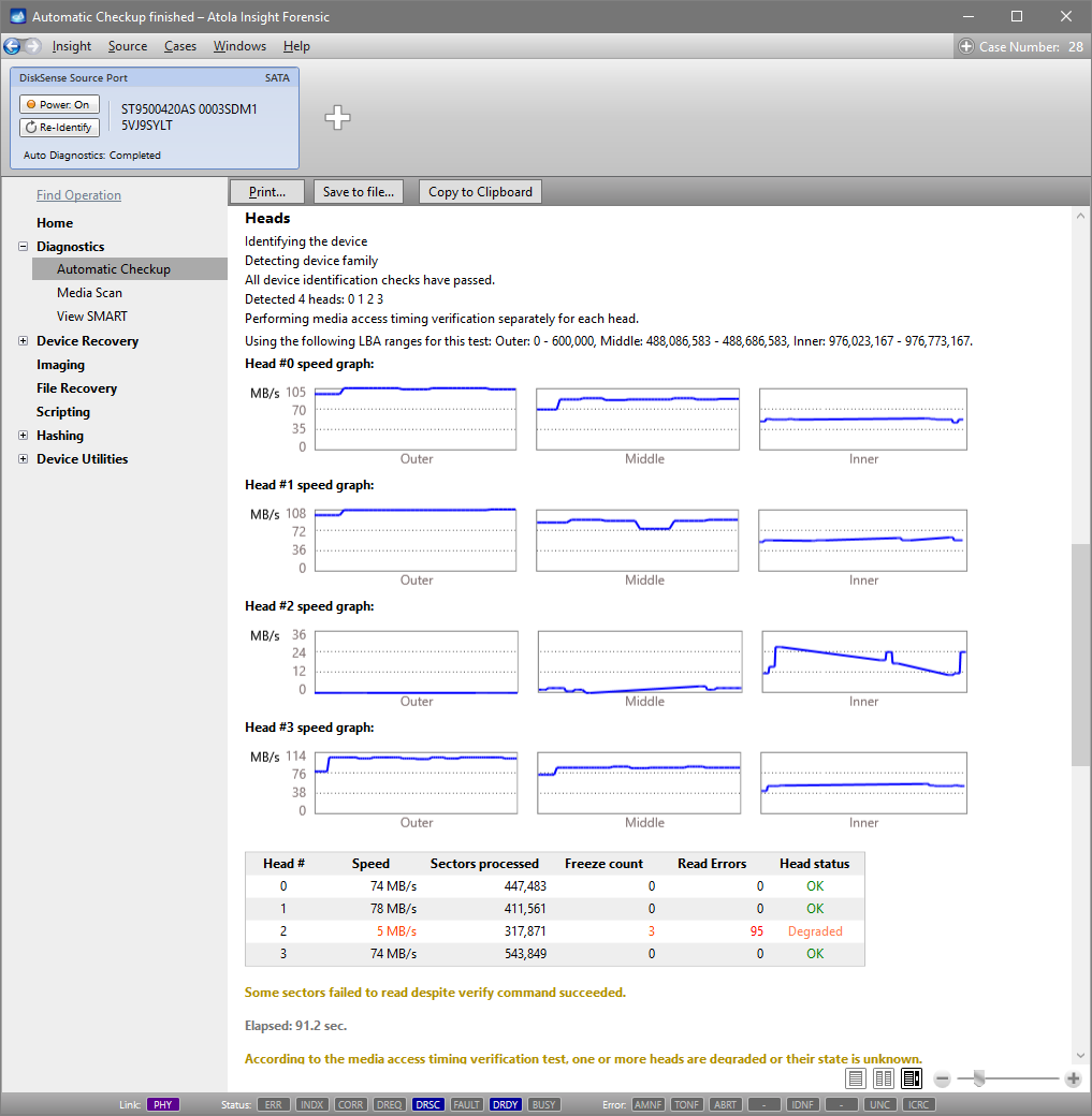
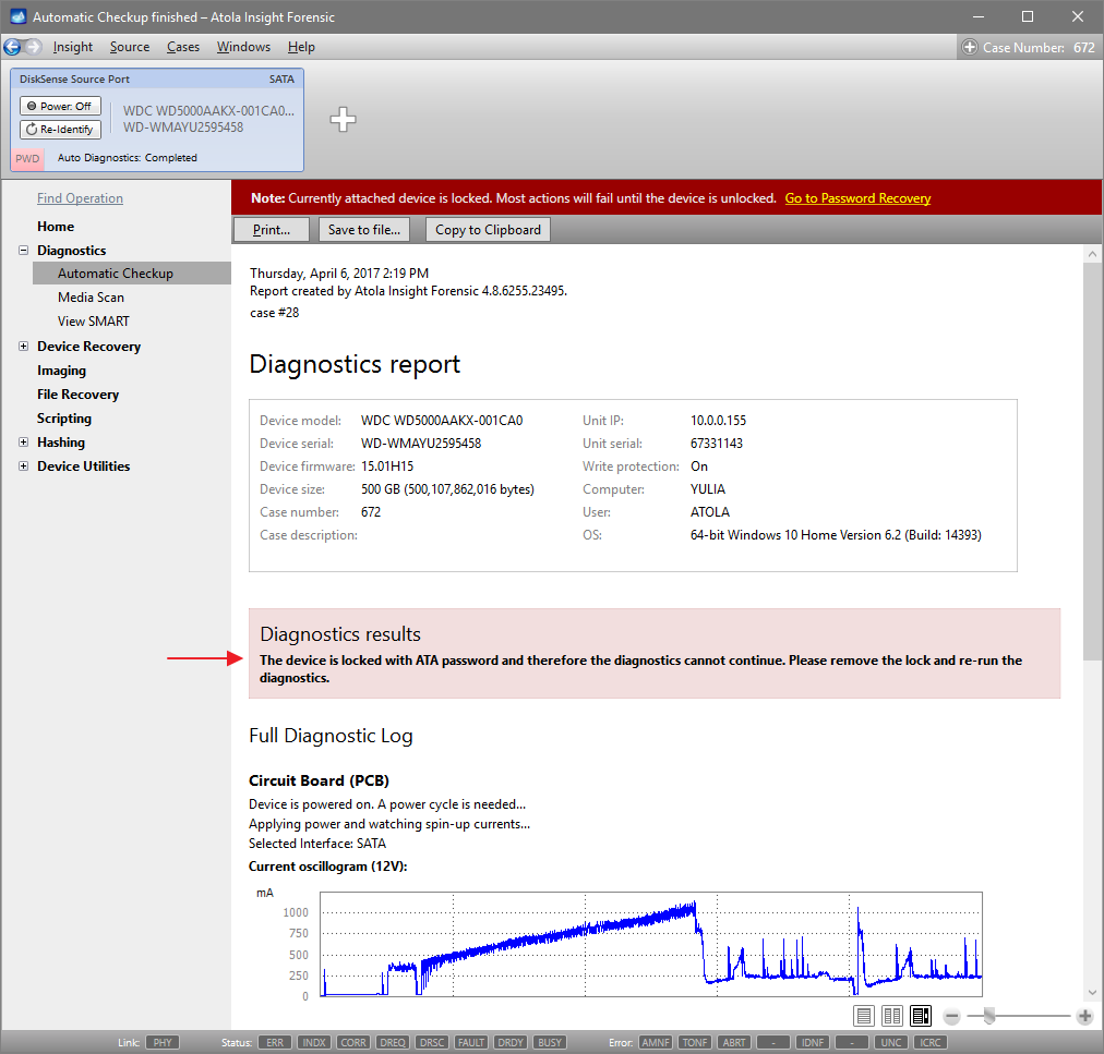
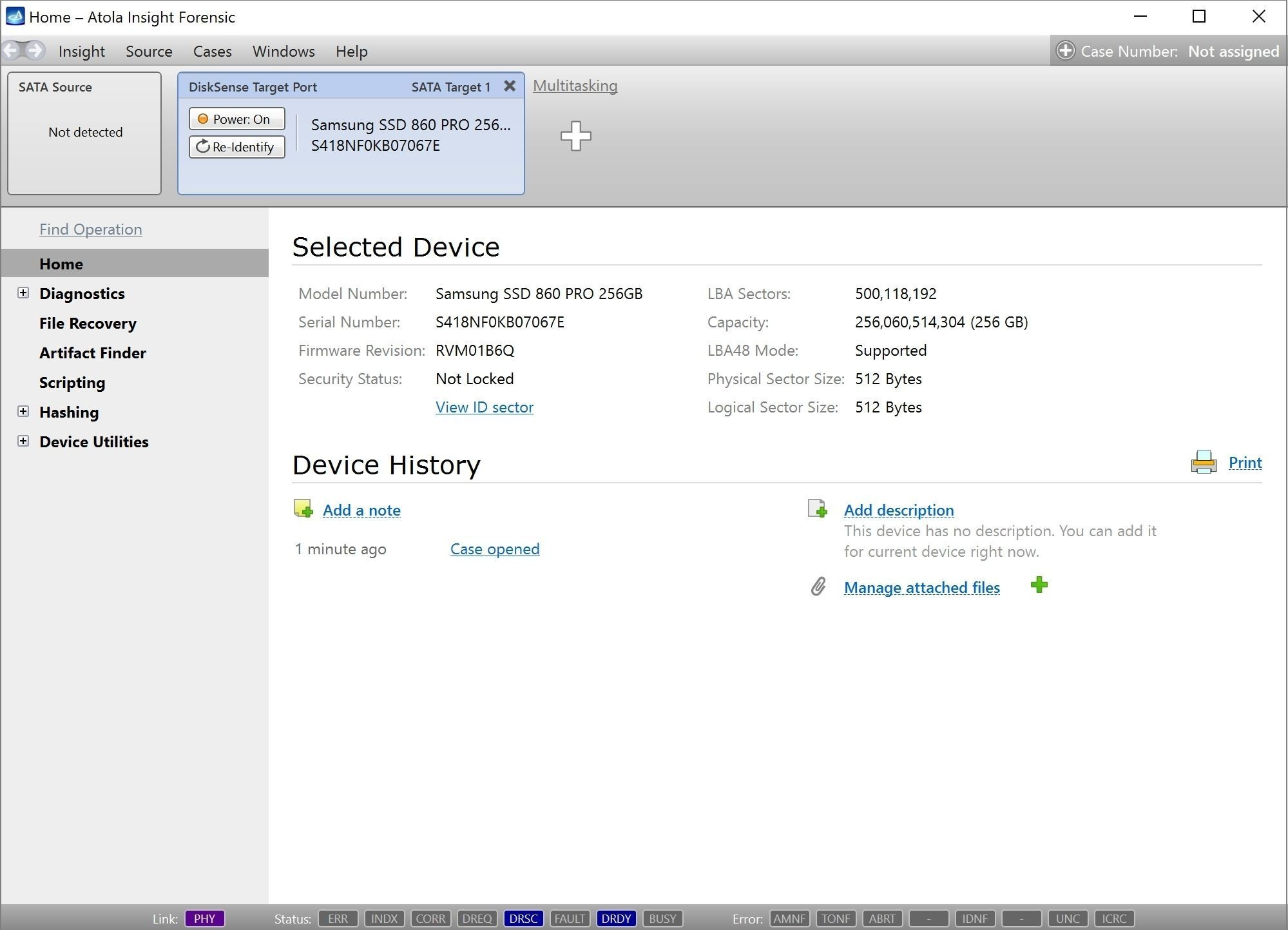
Step 3. Diagnose first before imaging.
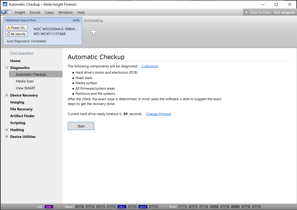
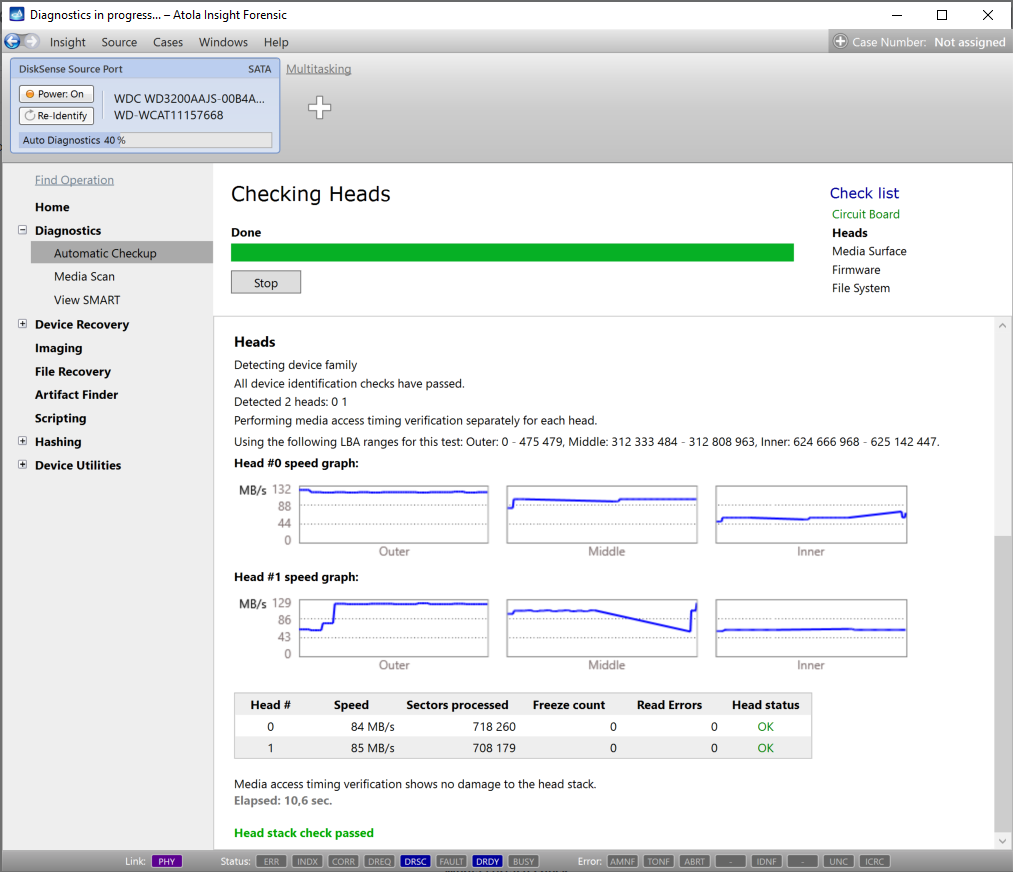
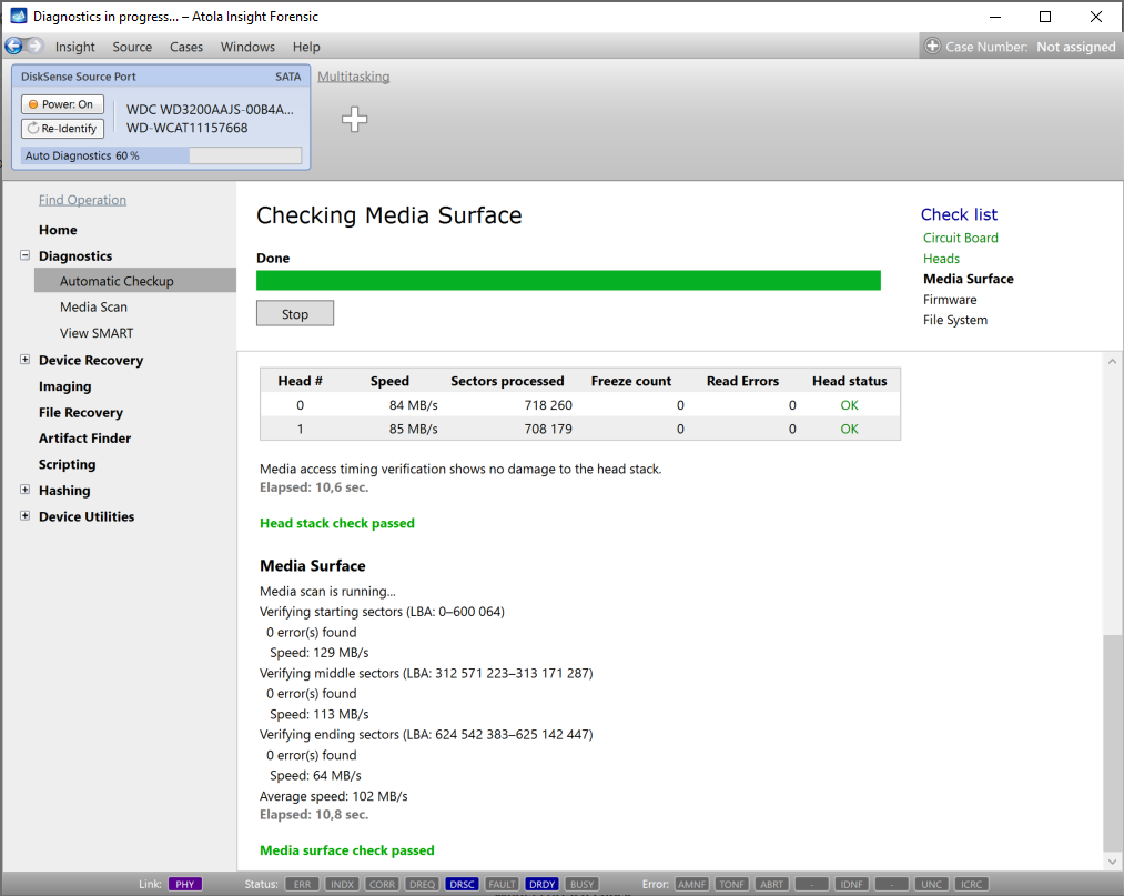
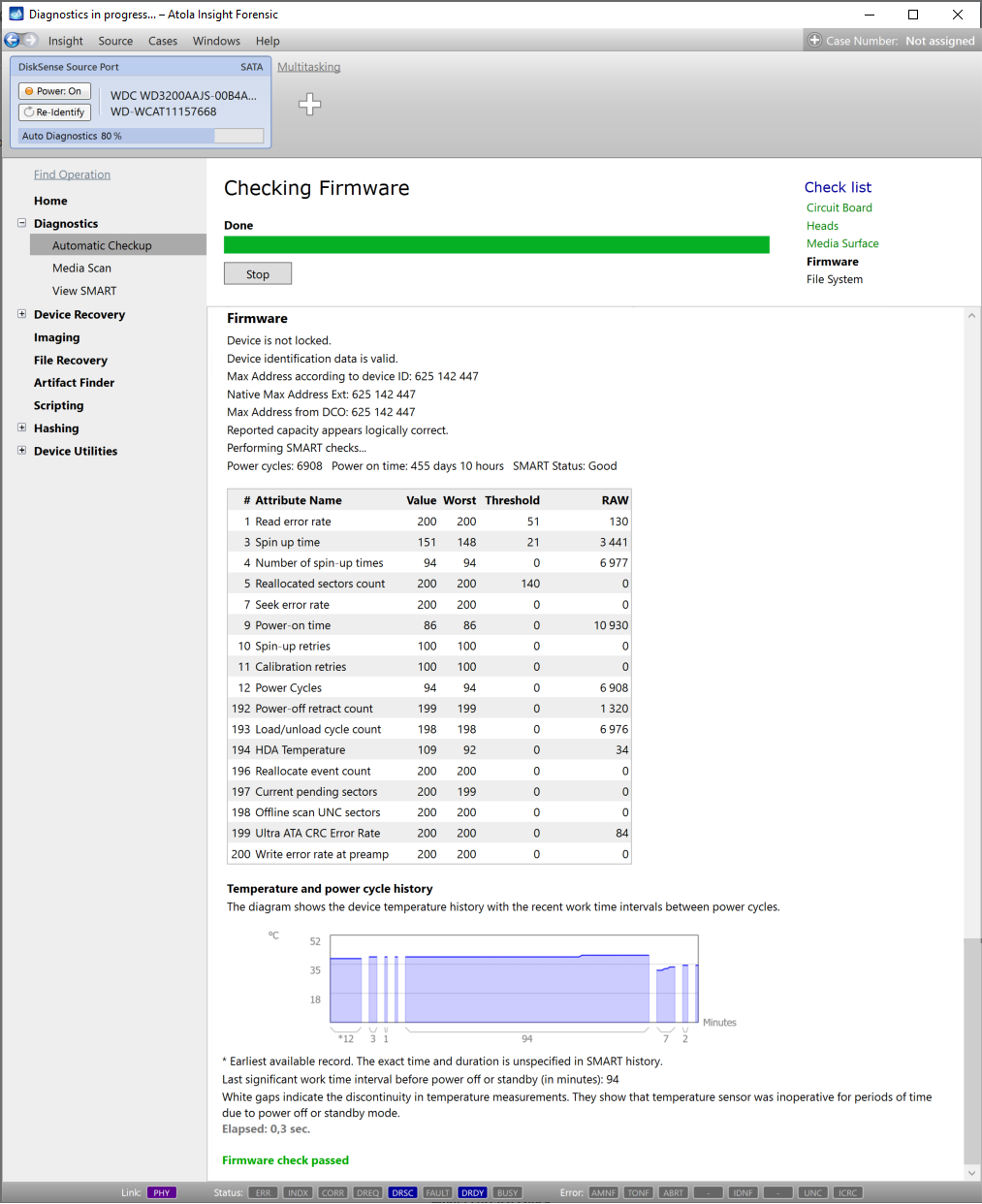
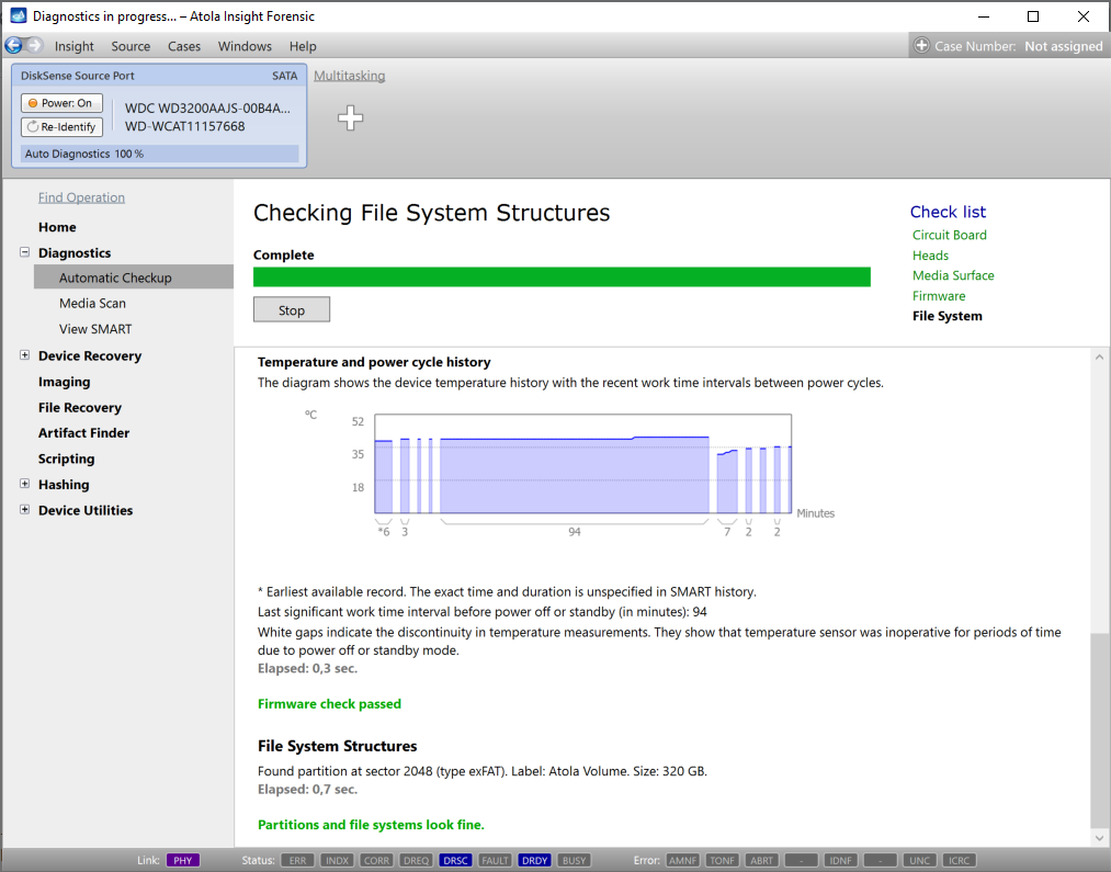
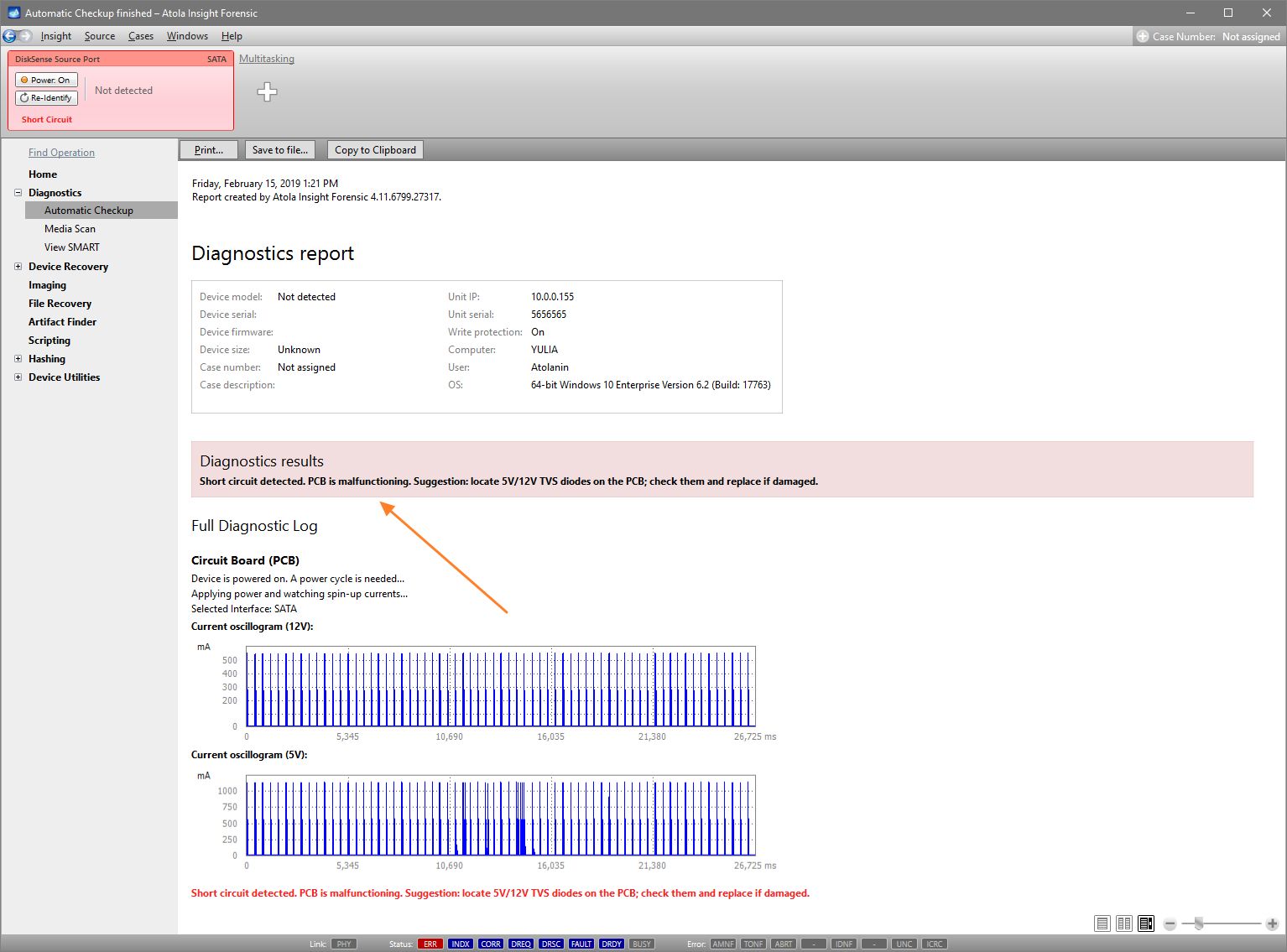
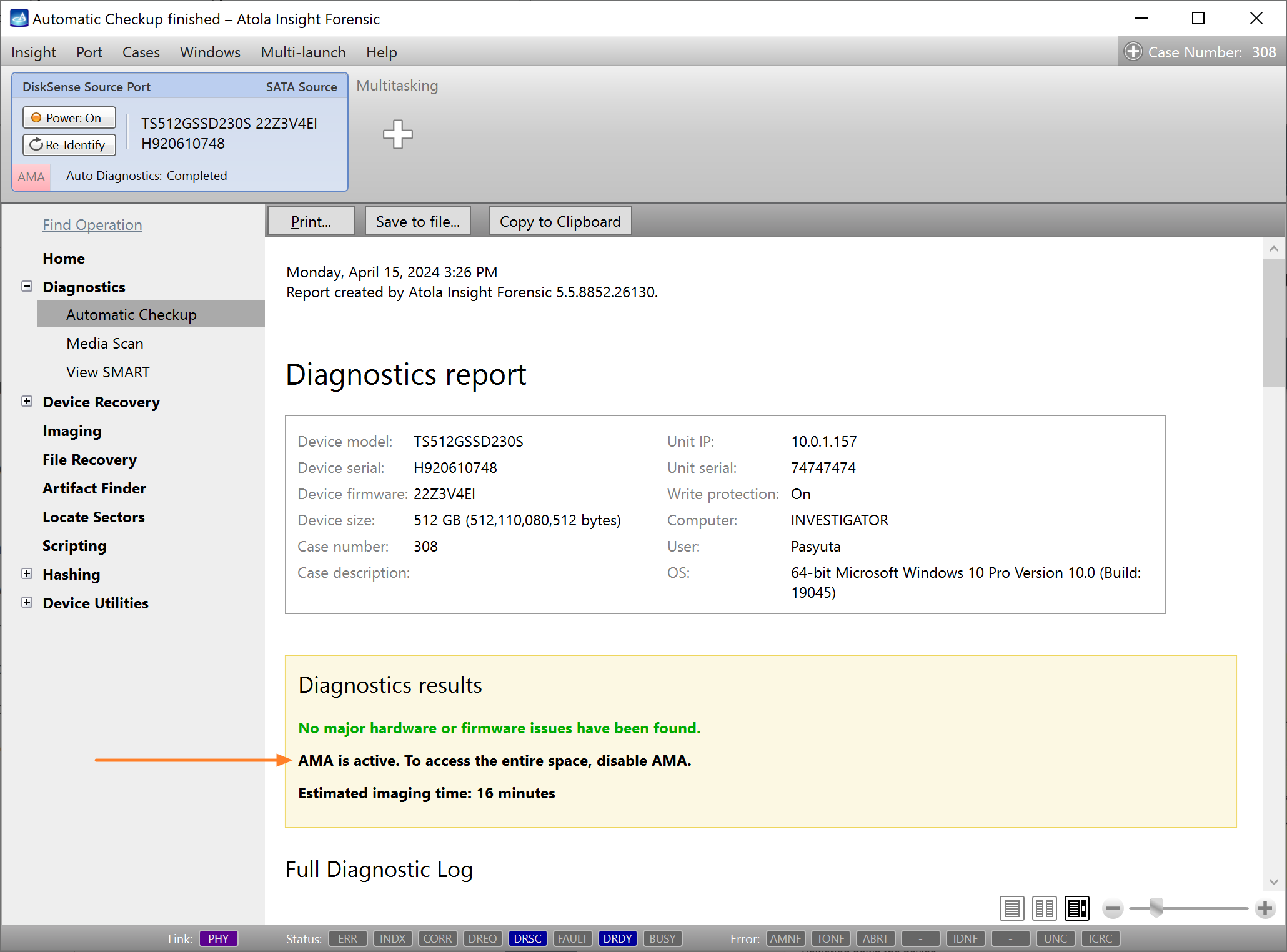
Presumably, we know nothing about the source device and its state. Maybe it is a good working drive, or maybe it is not. It may be a damaged one or it may die in a few hours. That is why we should begin with Automatic Checkup.
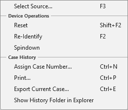
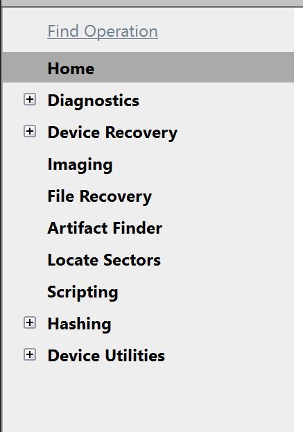
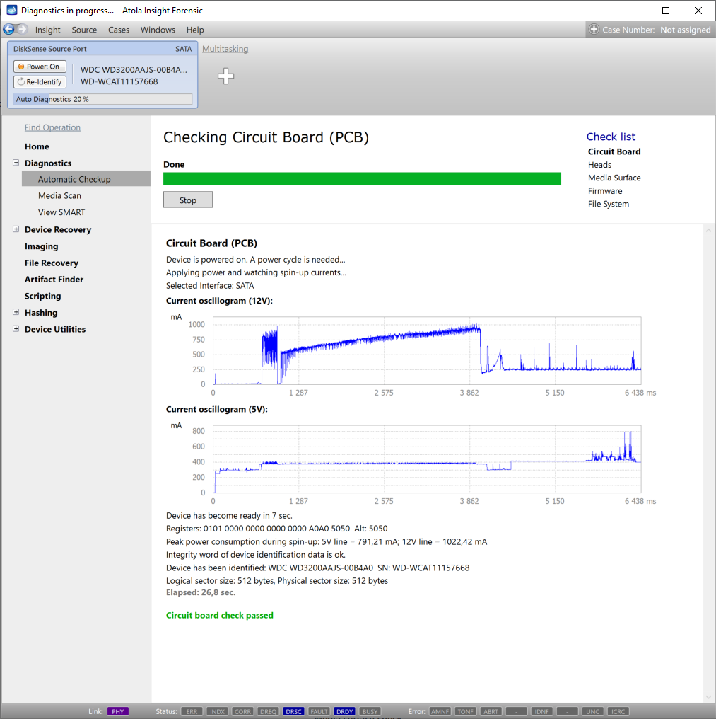
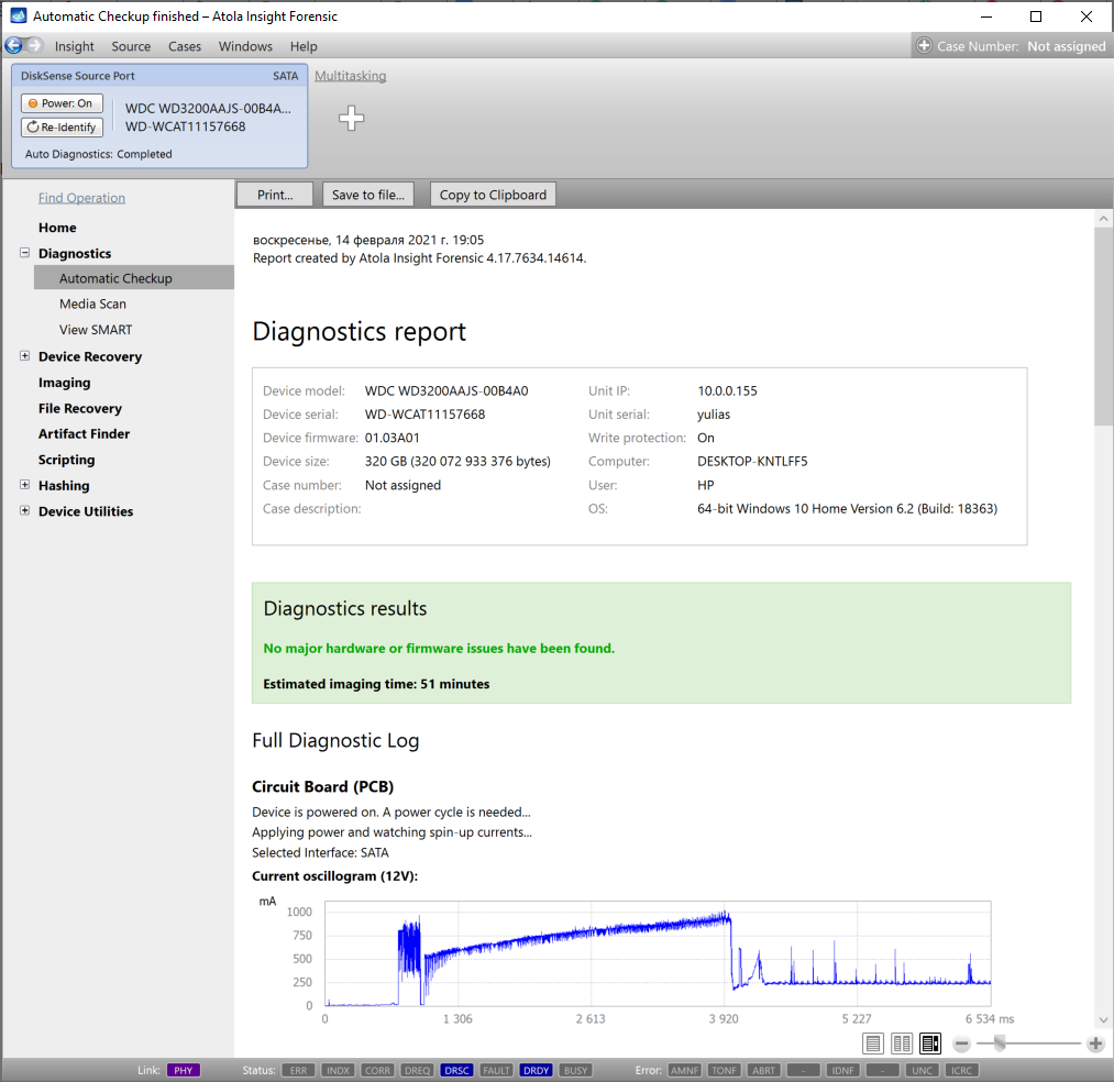
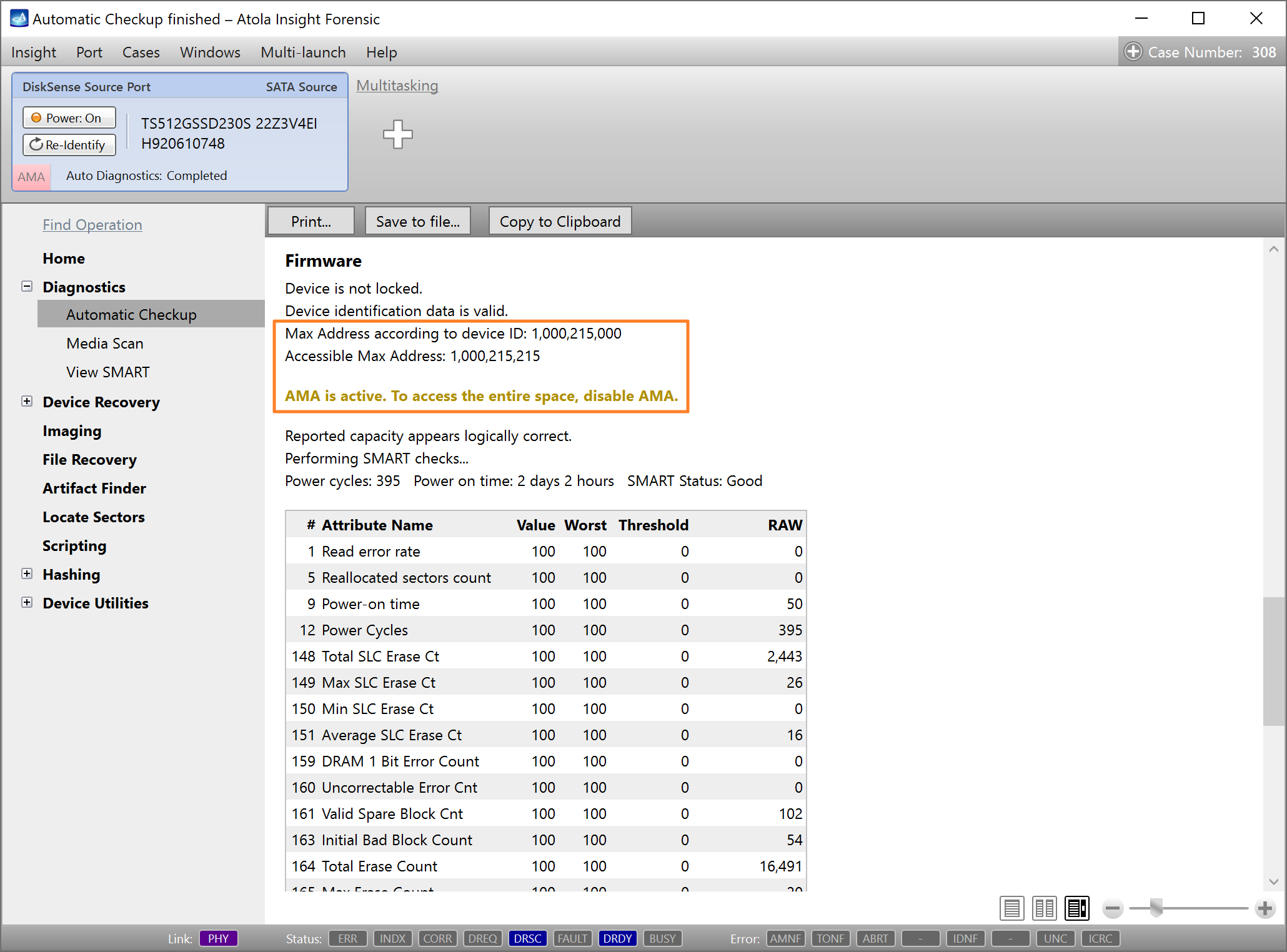
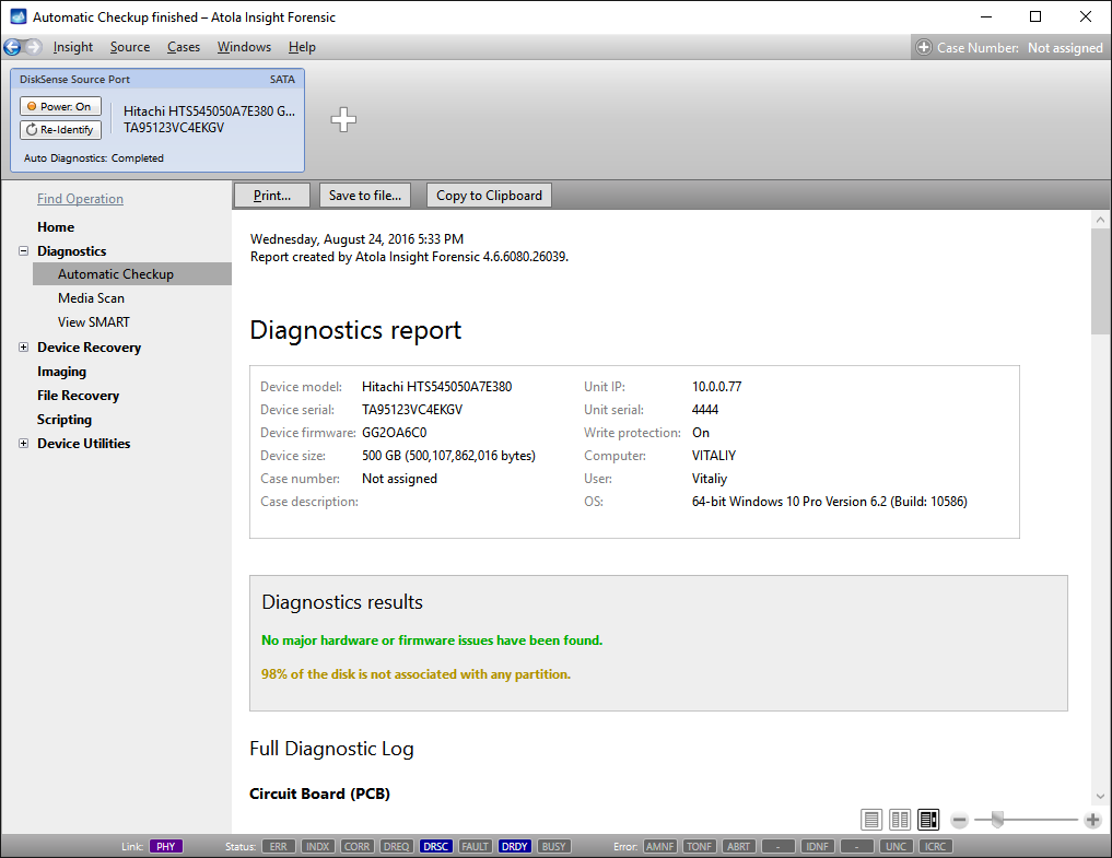
Go to Diagnostics > Automatic checkup, and then click the Start button.
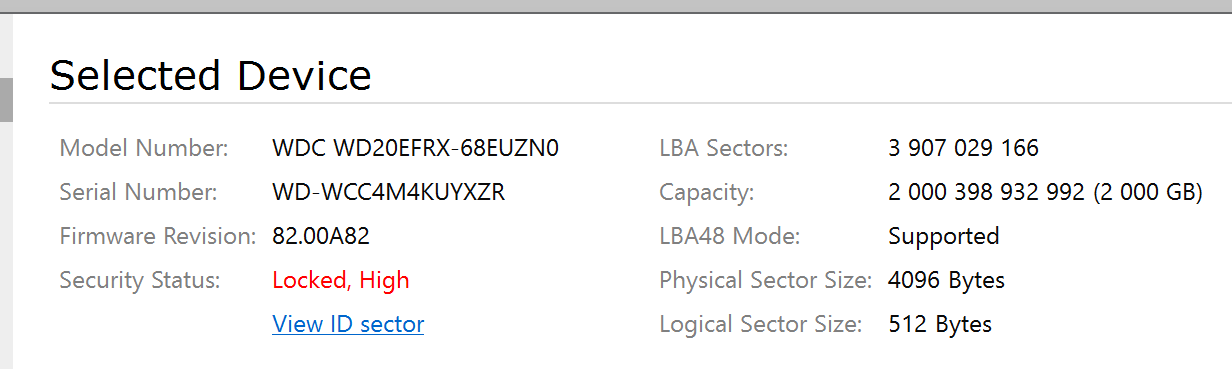
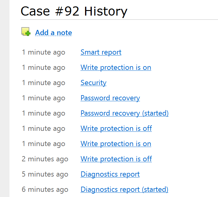
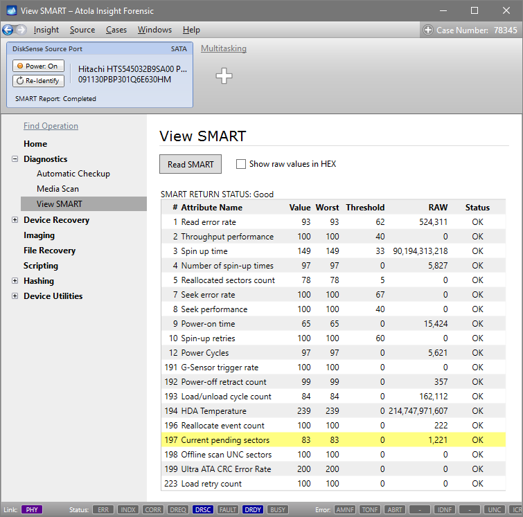
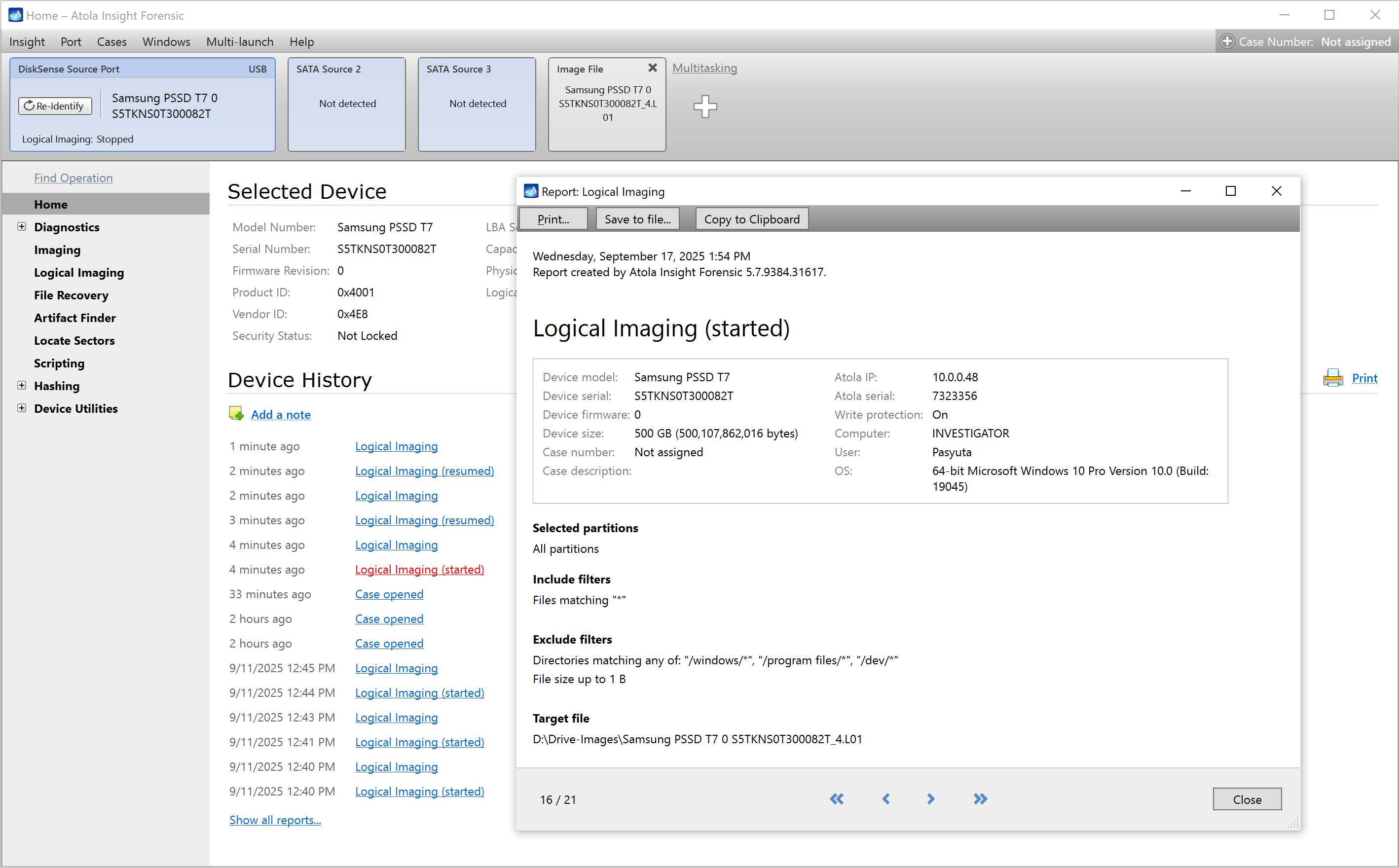
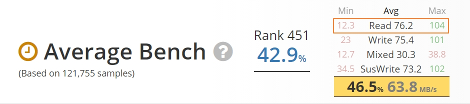
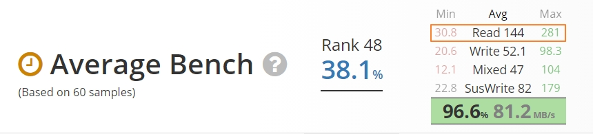
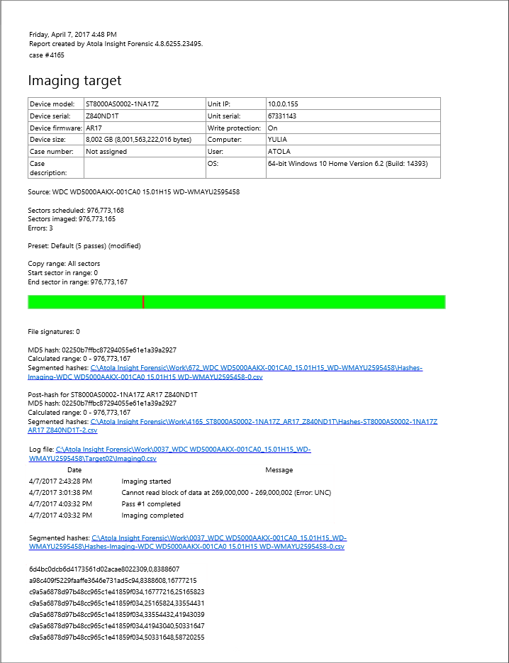
It will take a couple of minutes to get to the Diagnostics report. In this particular case, we see that the source drive is in good state, and we can safely start imaging it.
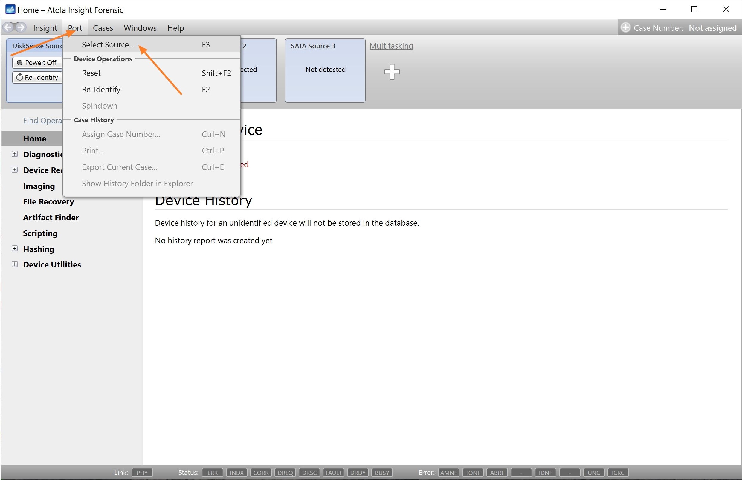
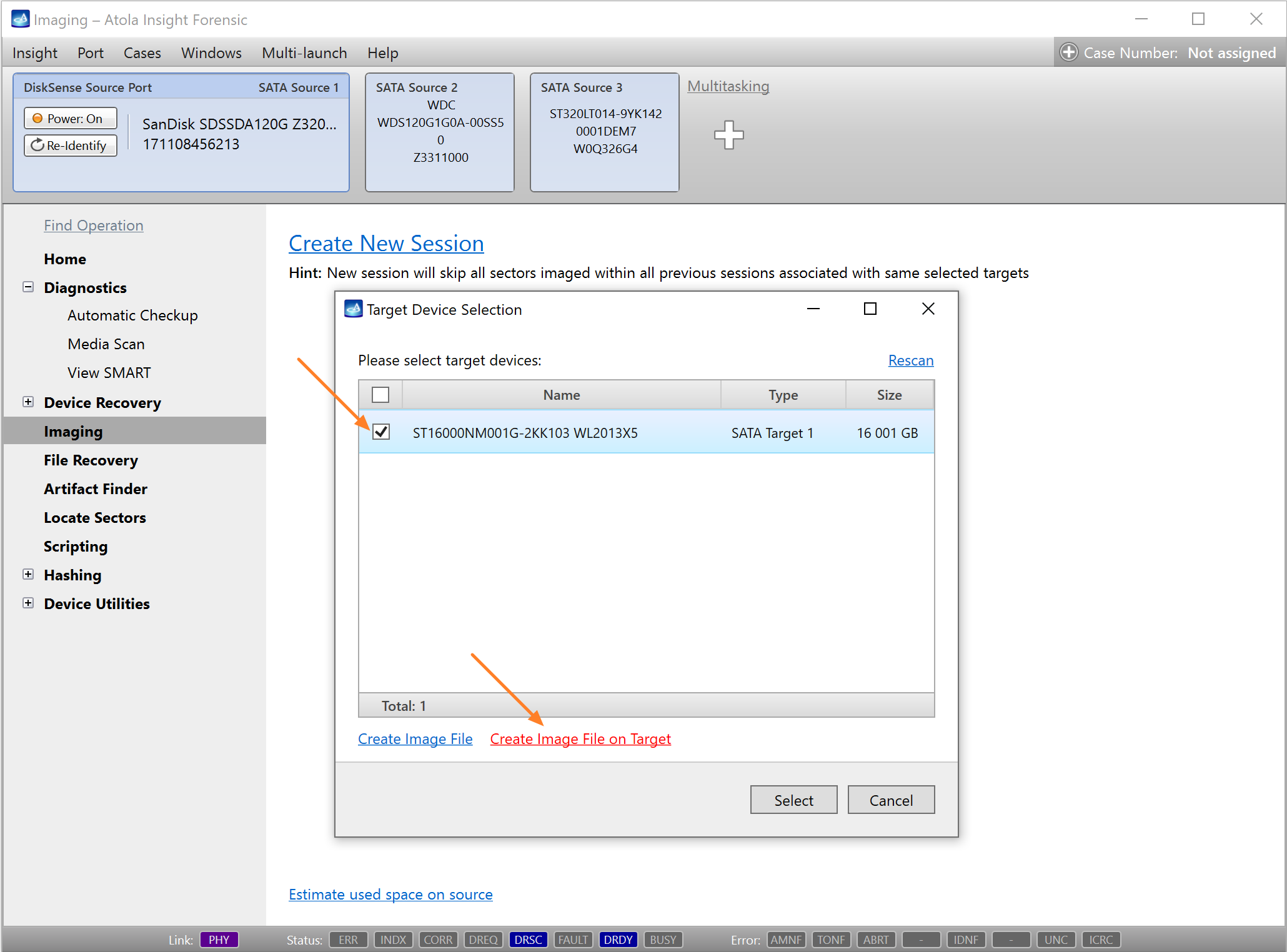
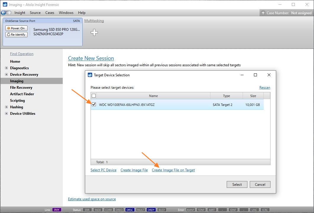
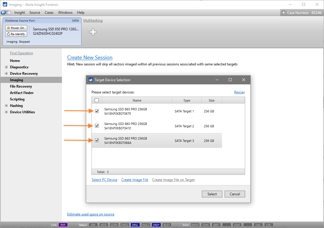
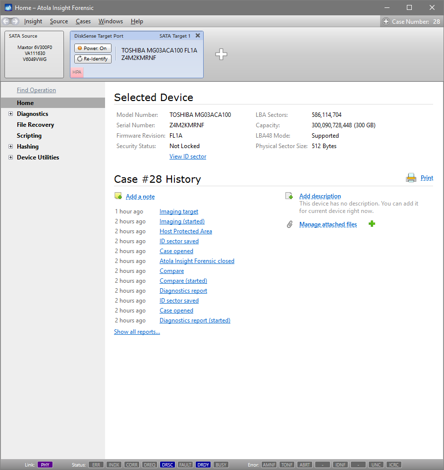
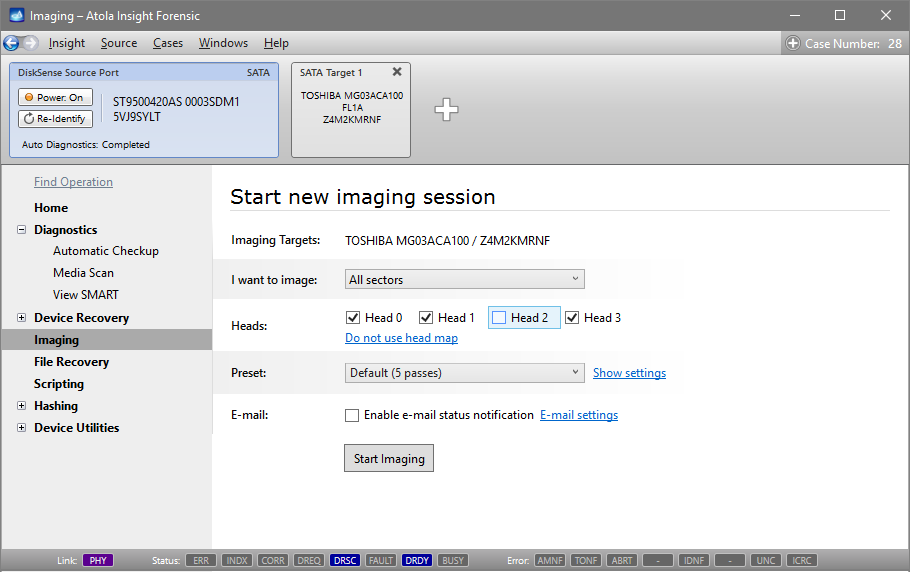
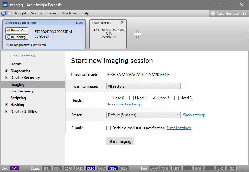
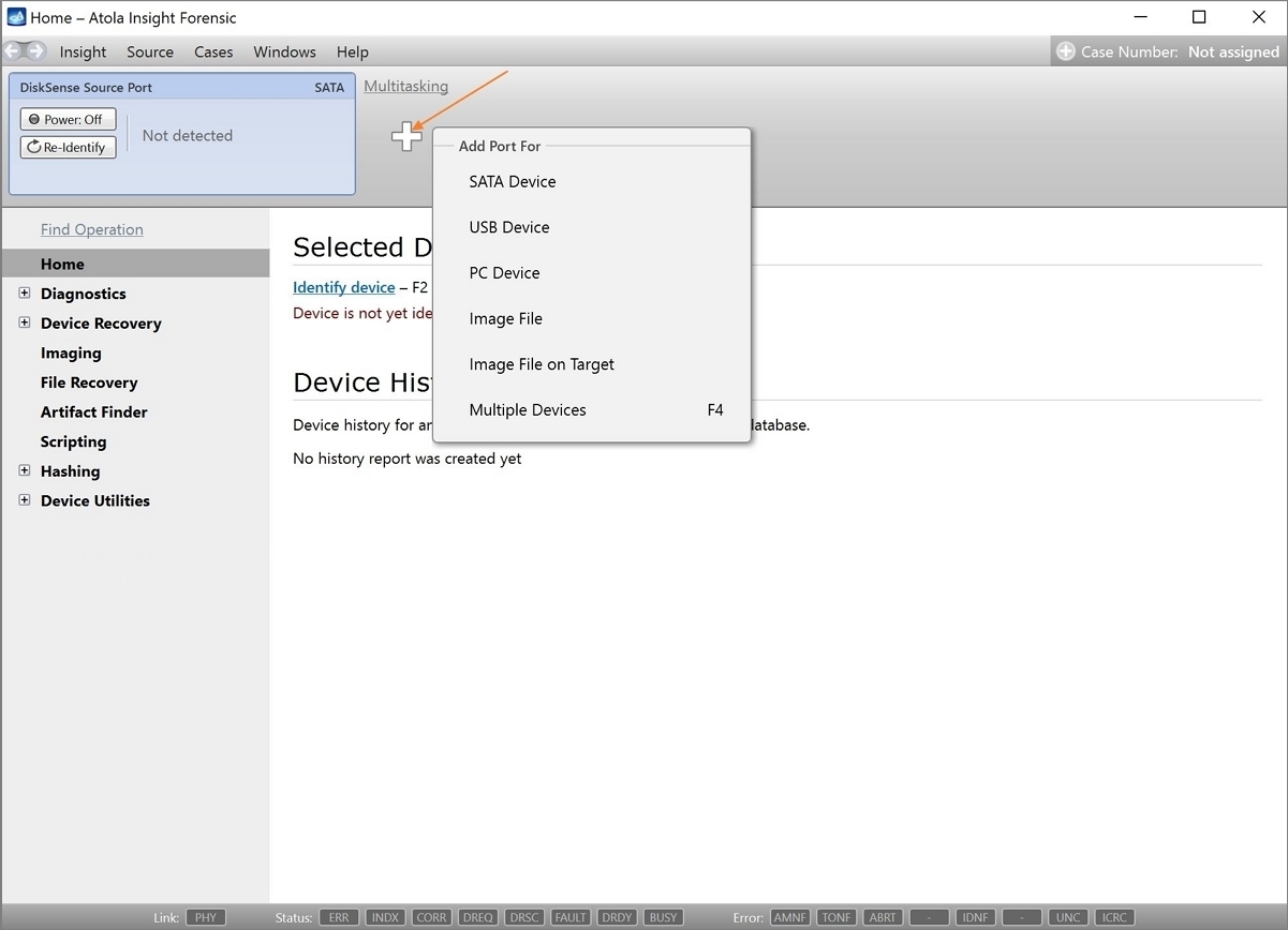
Step 4. Select the imaging targets.
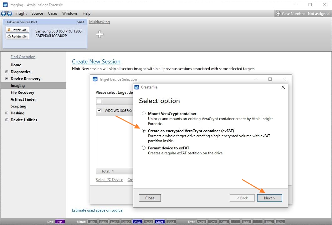
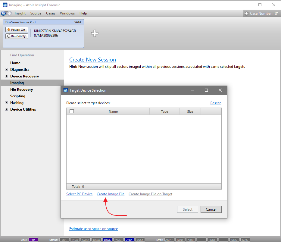
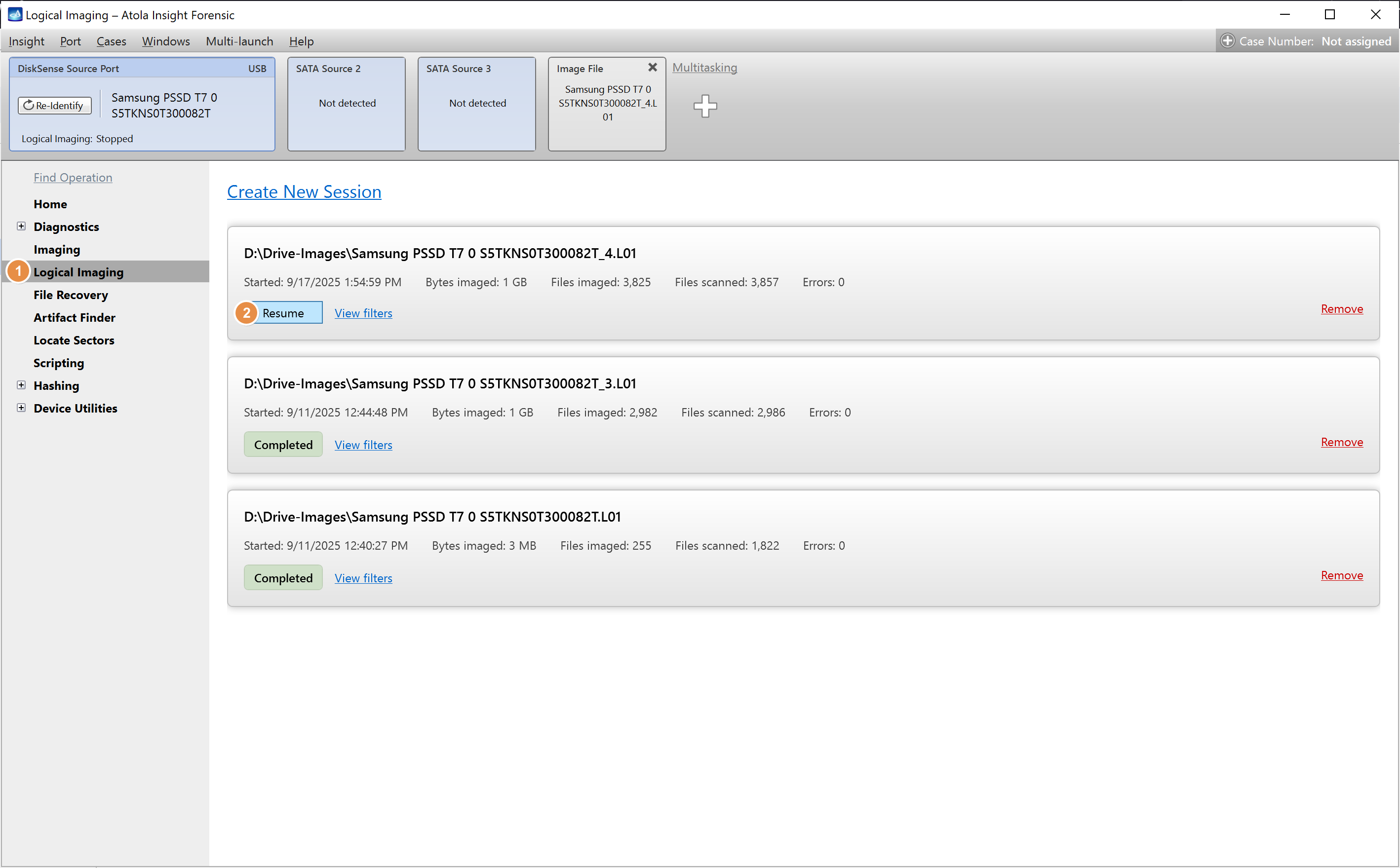
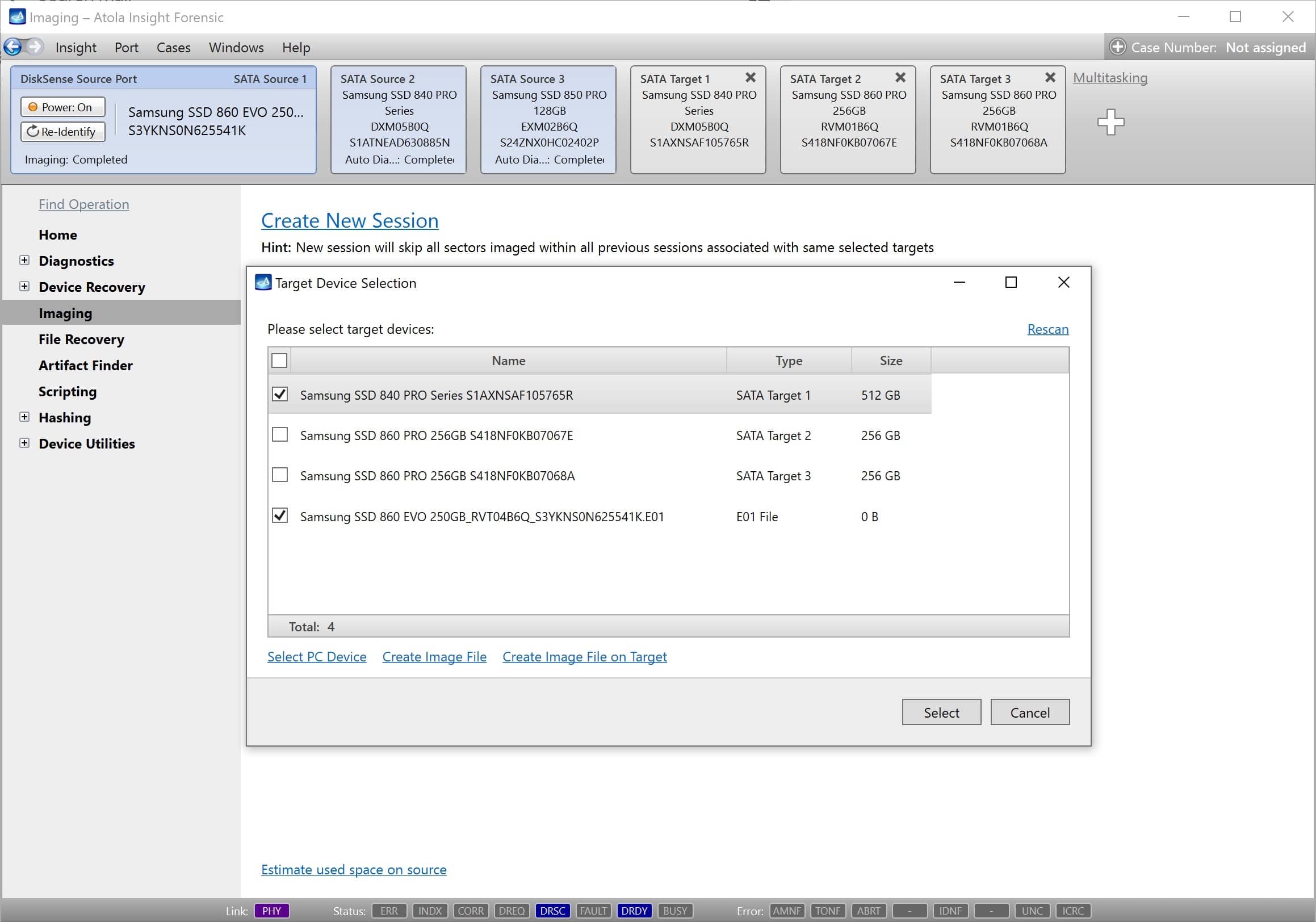
On the left, click Imaging and then Create New Session. You will be asked to select the imaging targets, including the following:
- Devices plugged into SATA/USB target ports of the DiskSense system
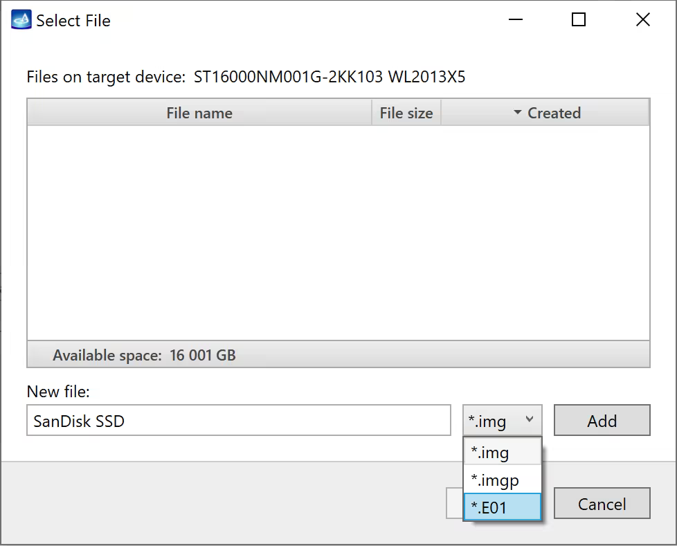
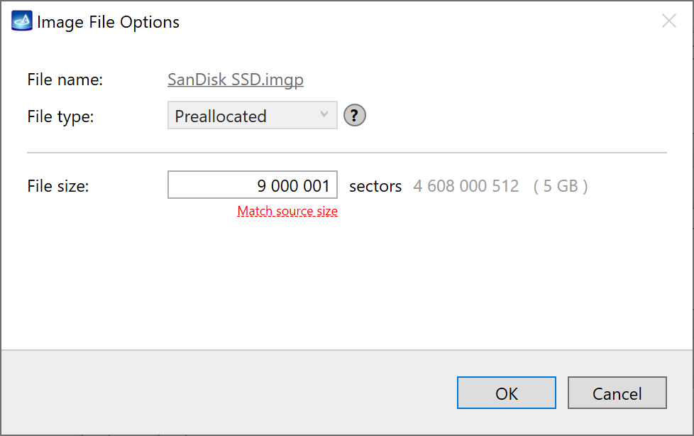
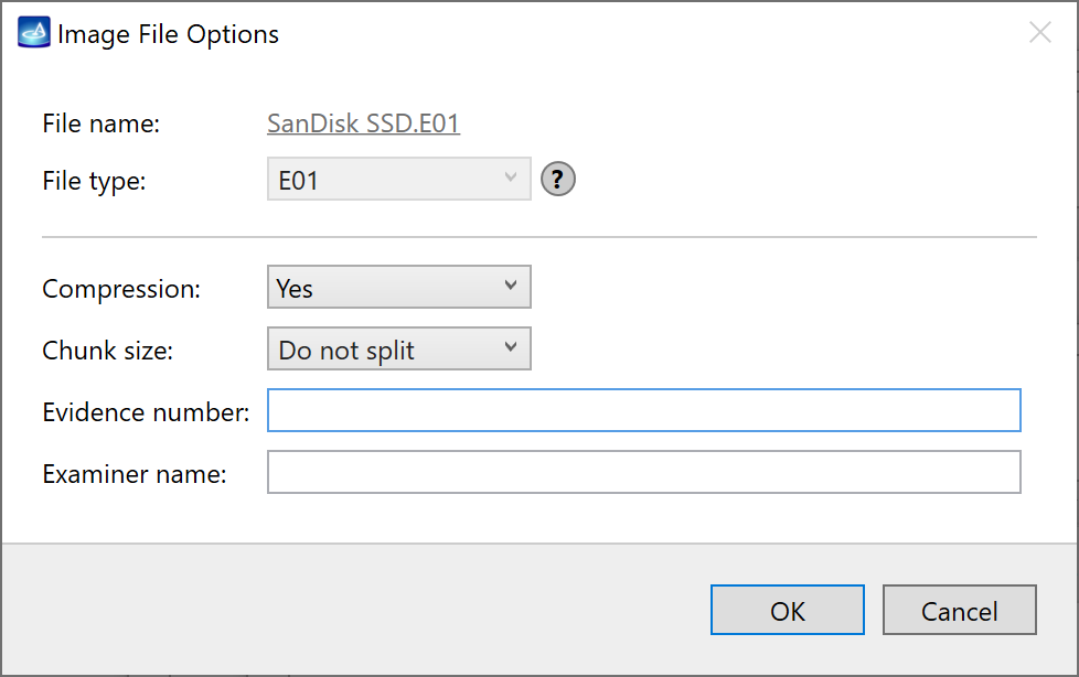
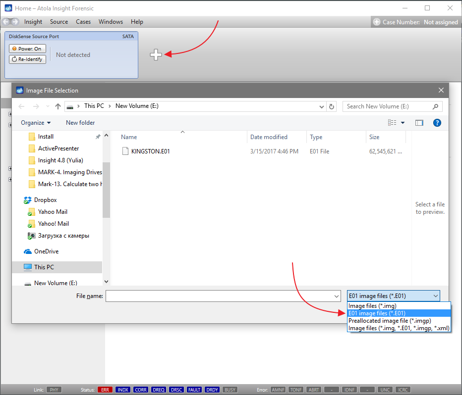
- Image files
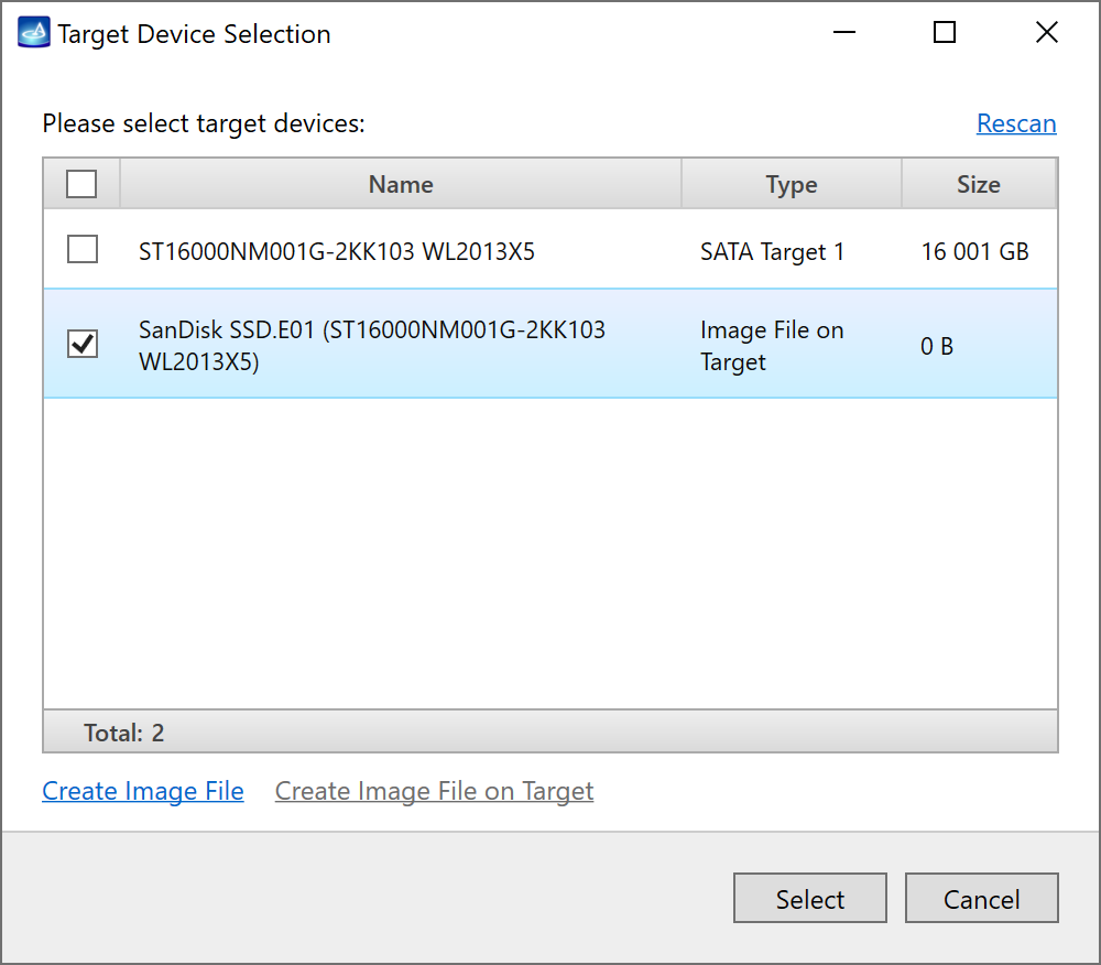
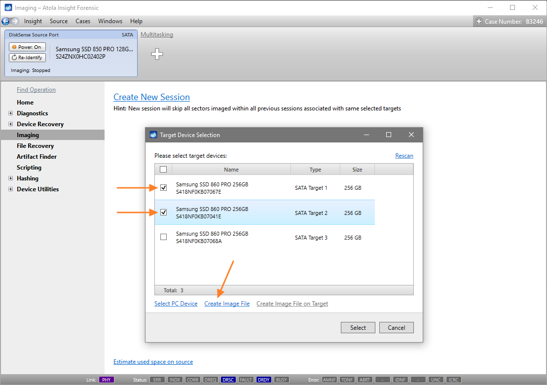
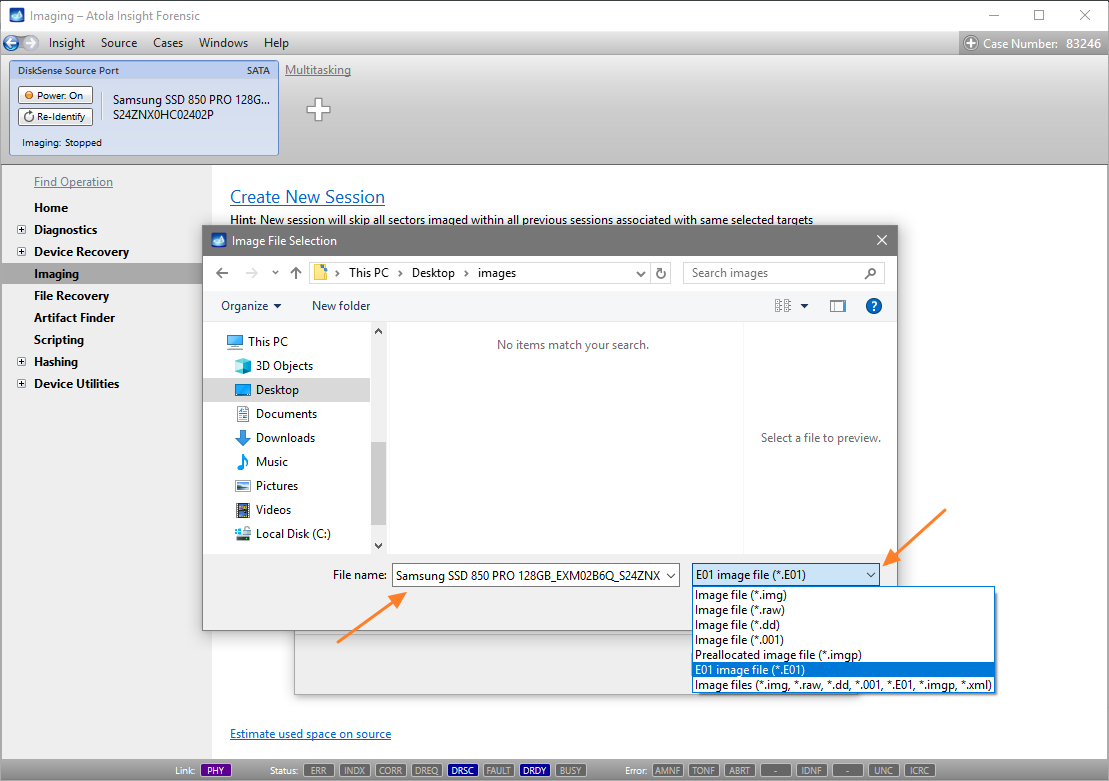
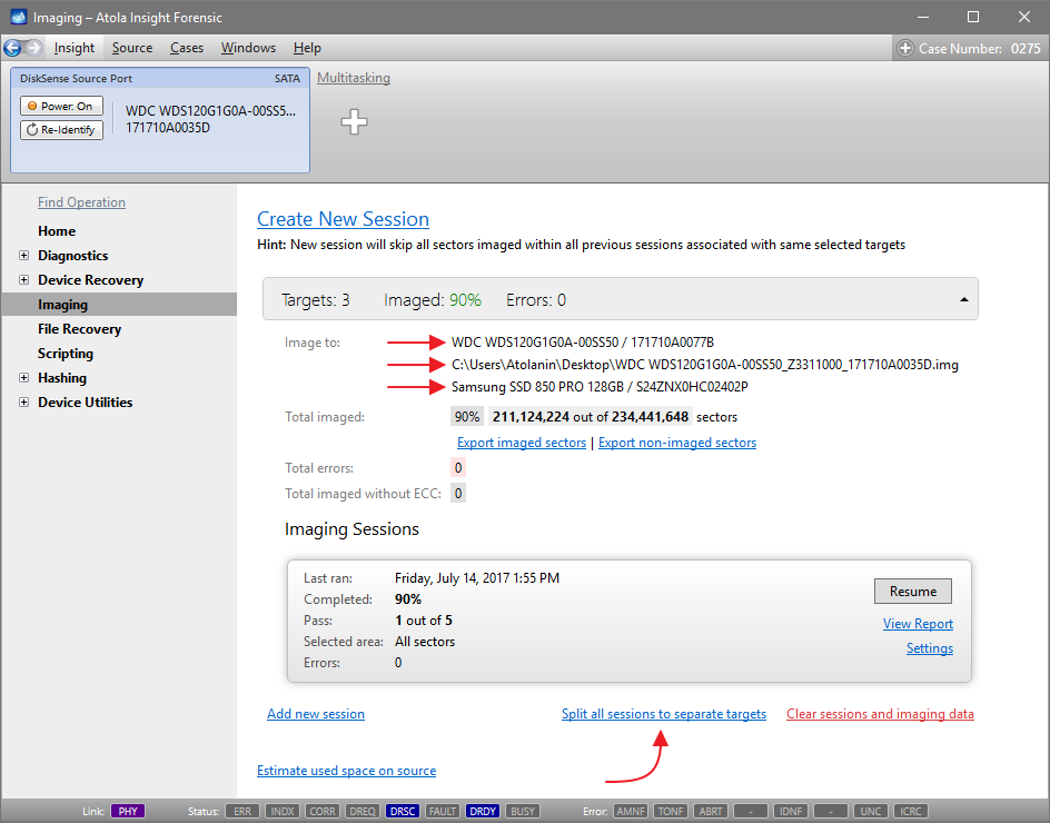
Let us take advantage of imaging into two targets at the same time: SATA target drive and image file.
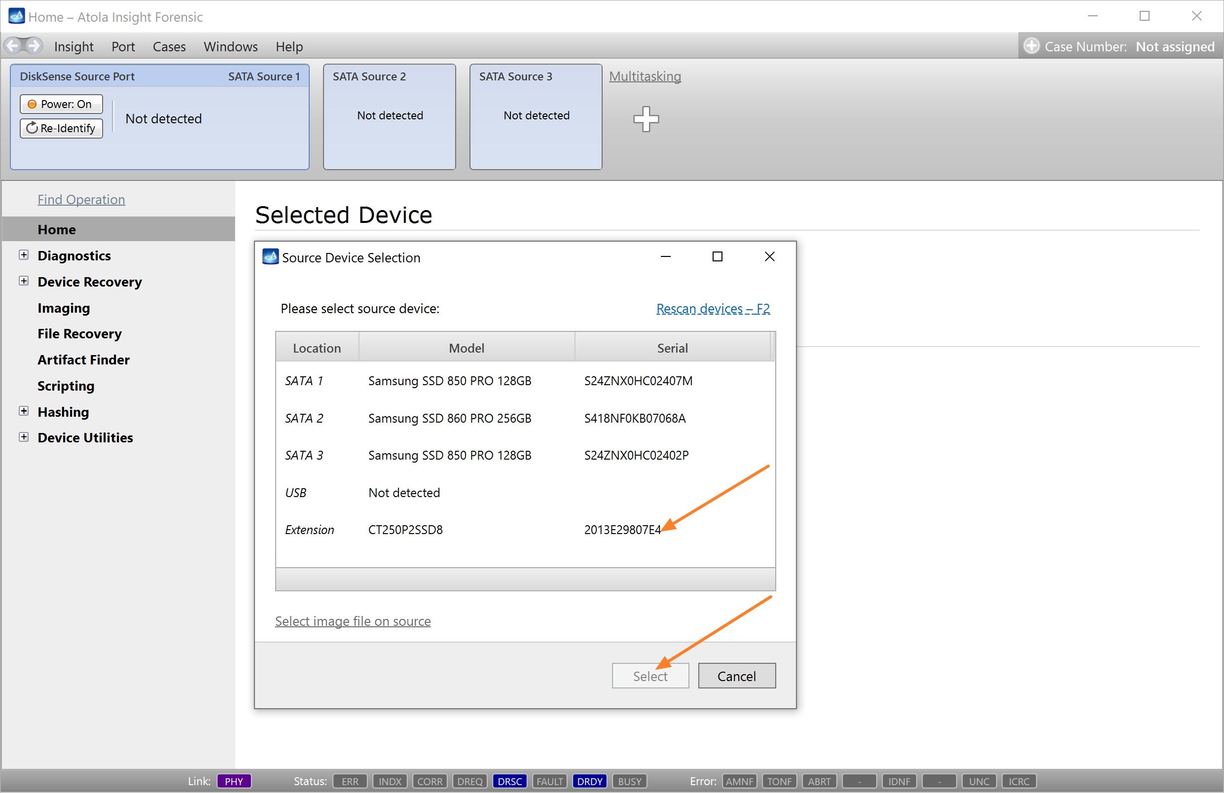
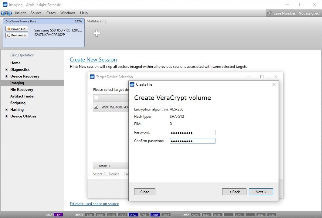
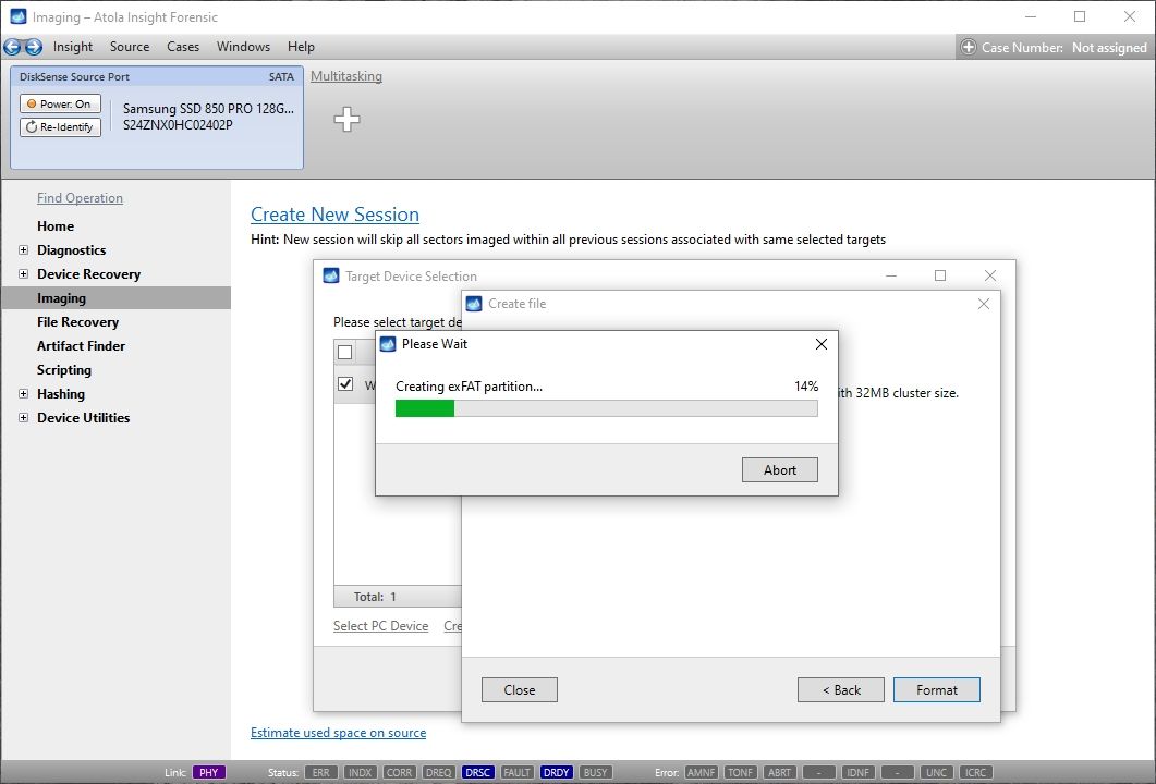
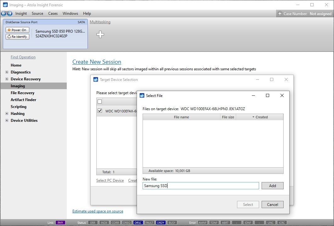
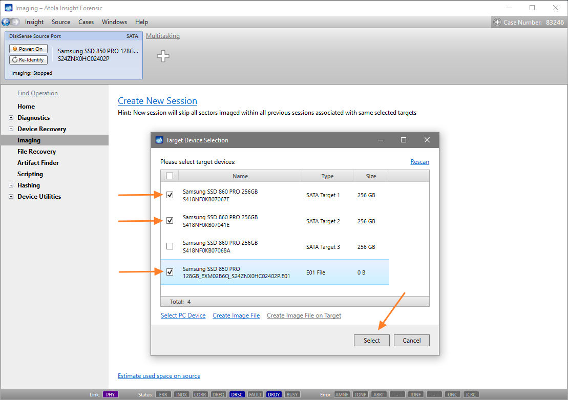
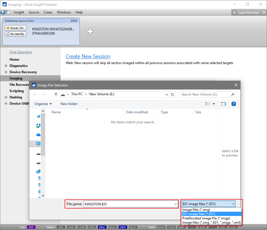
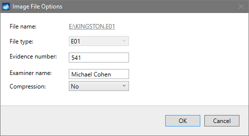
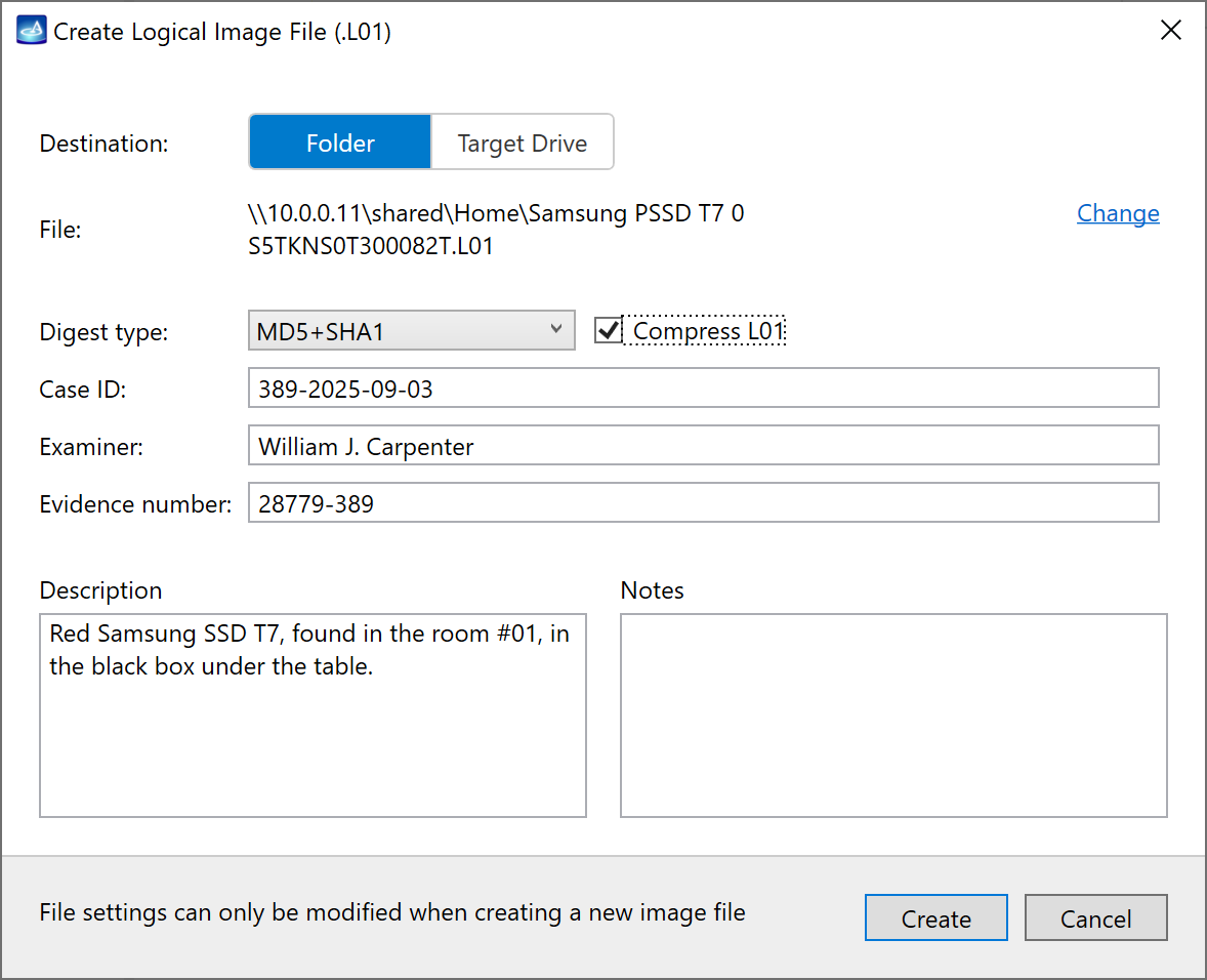
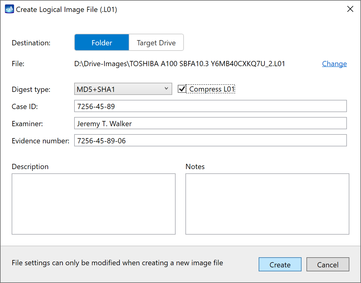
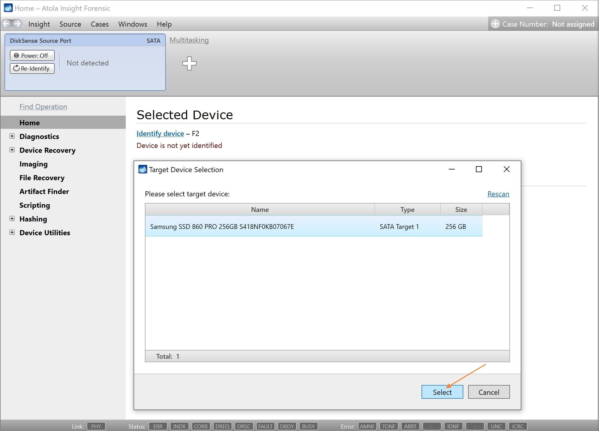
Click Create Image File and then confirm a selected filename. Then select the SATA Target 1 device. In the end, you will get a screen like this:
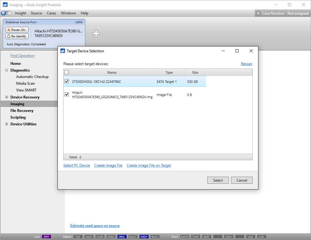
Click the Select button to confirm.
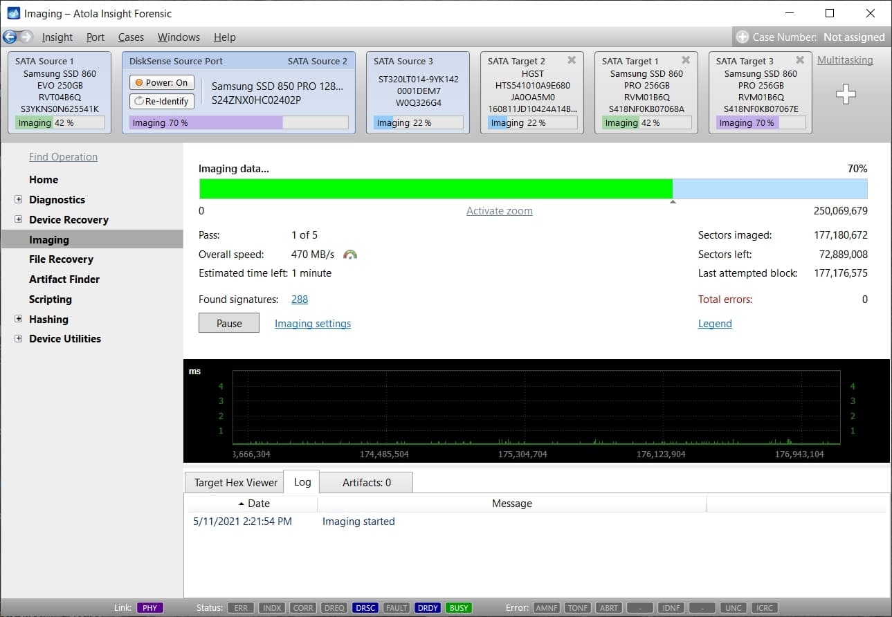
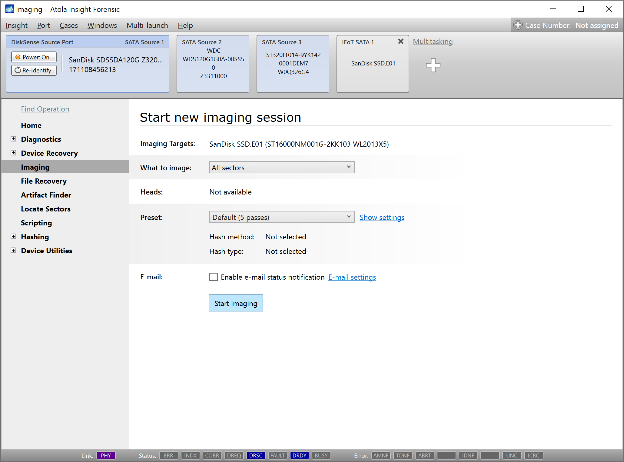
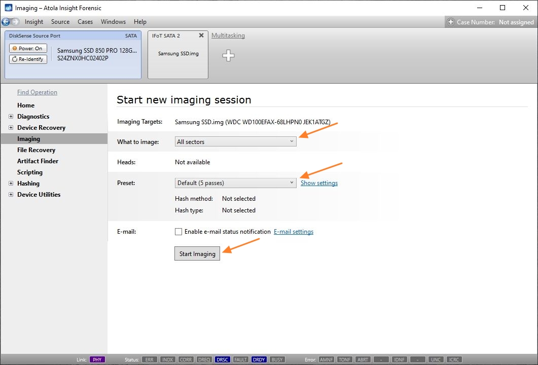
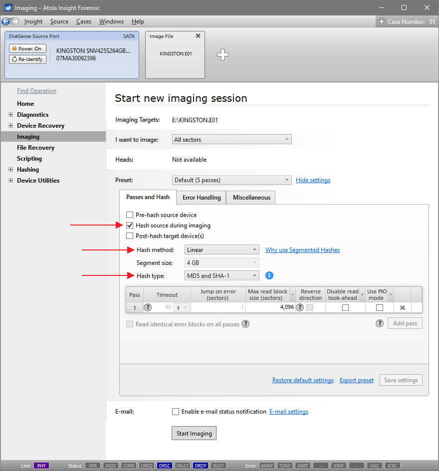
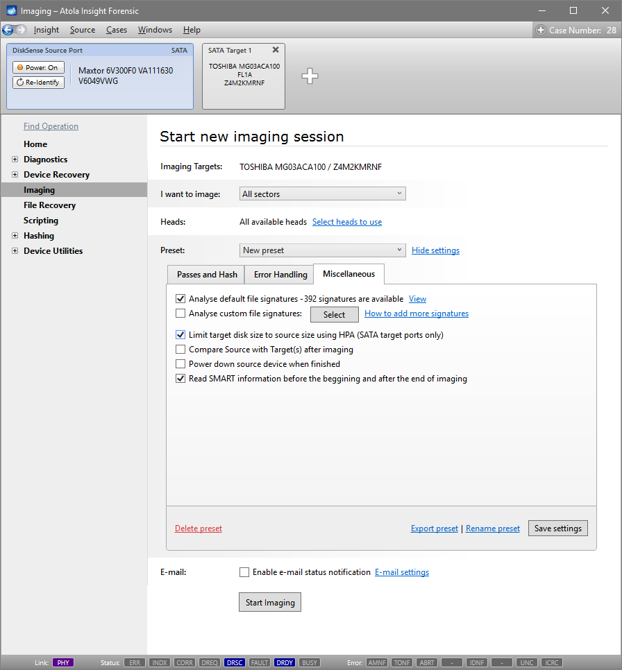
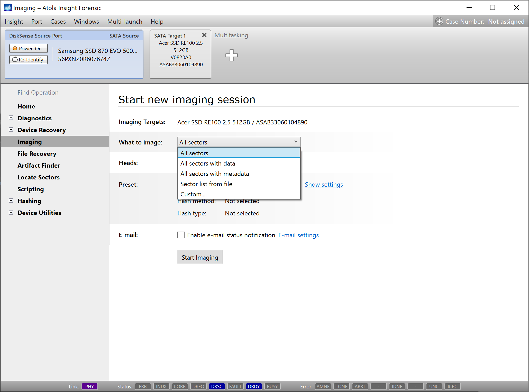
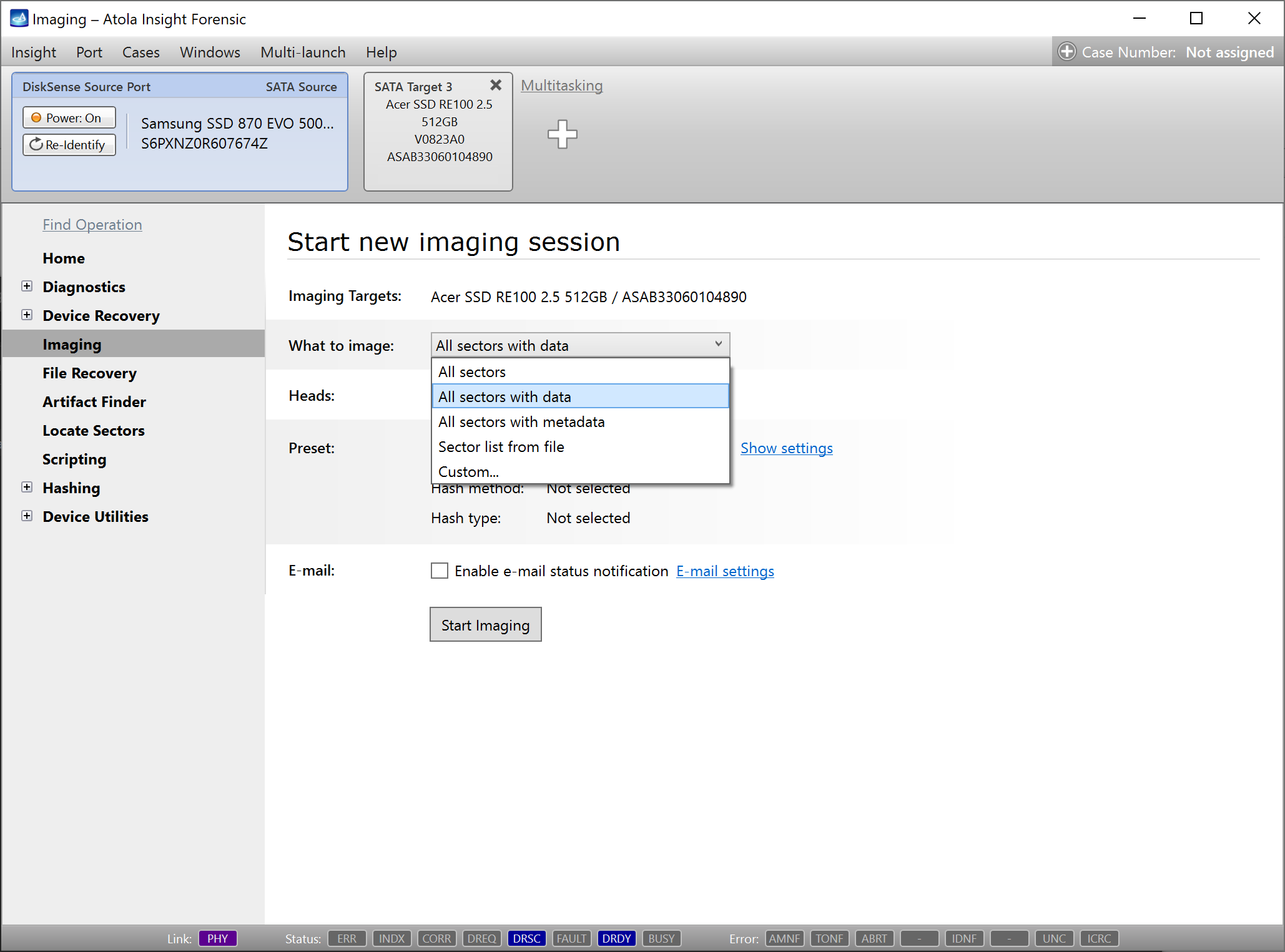
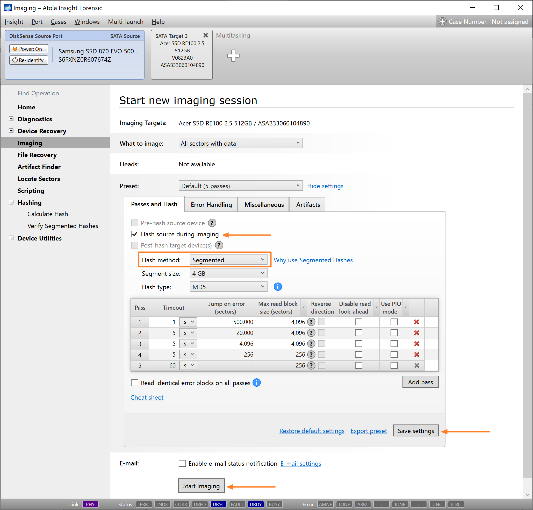
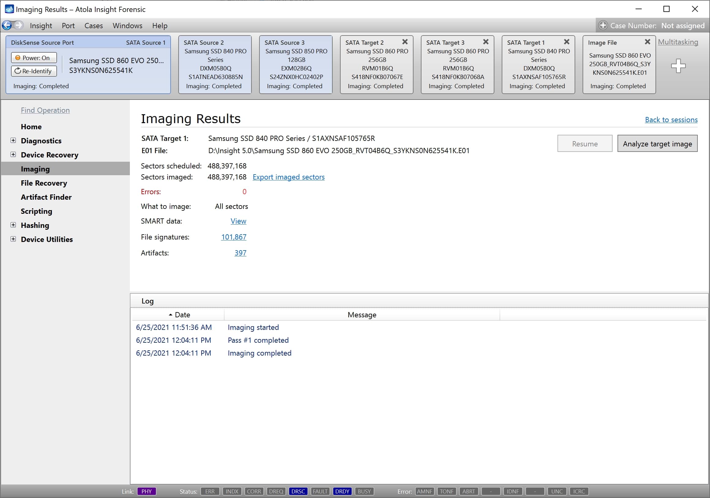
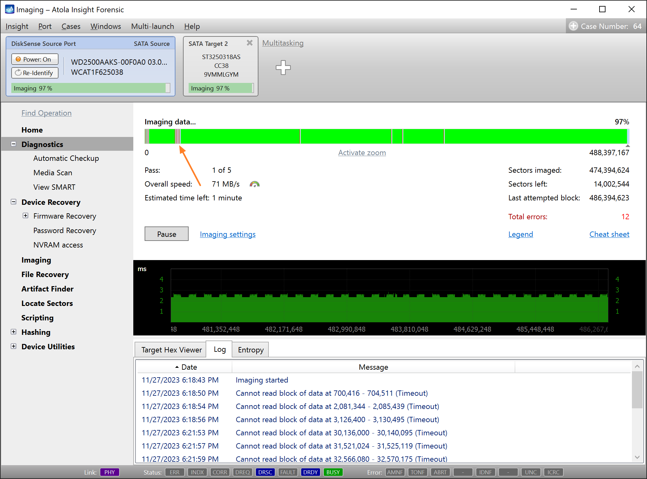
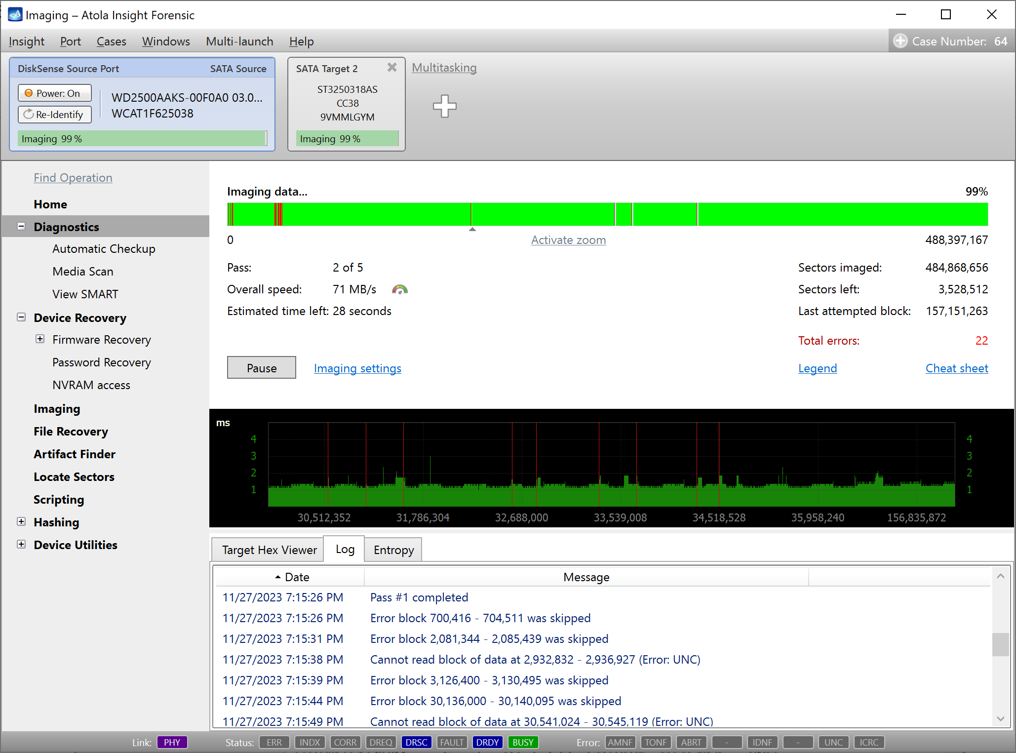
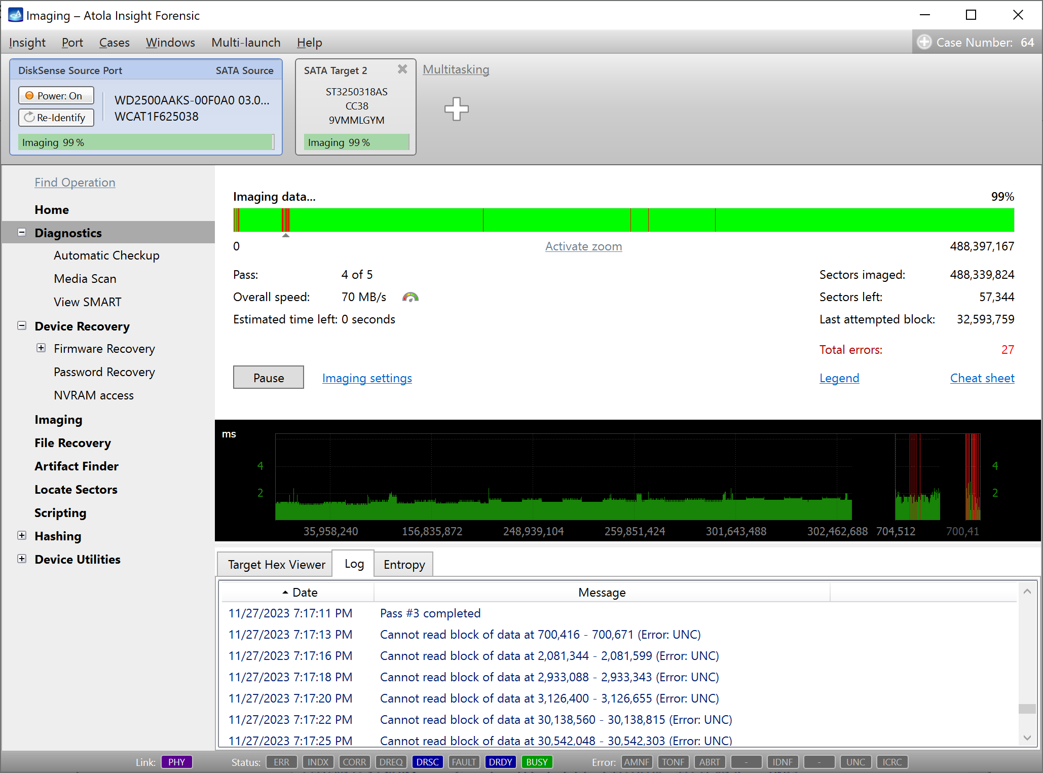
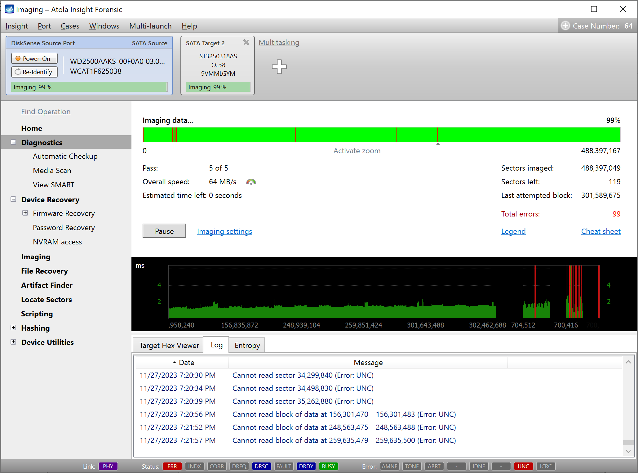
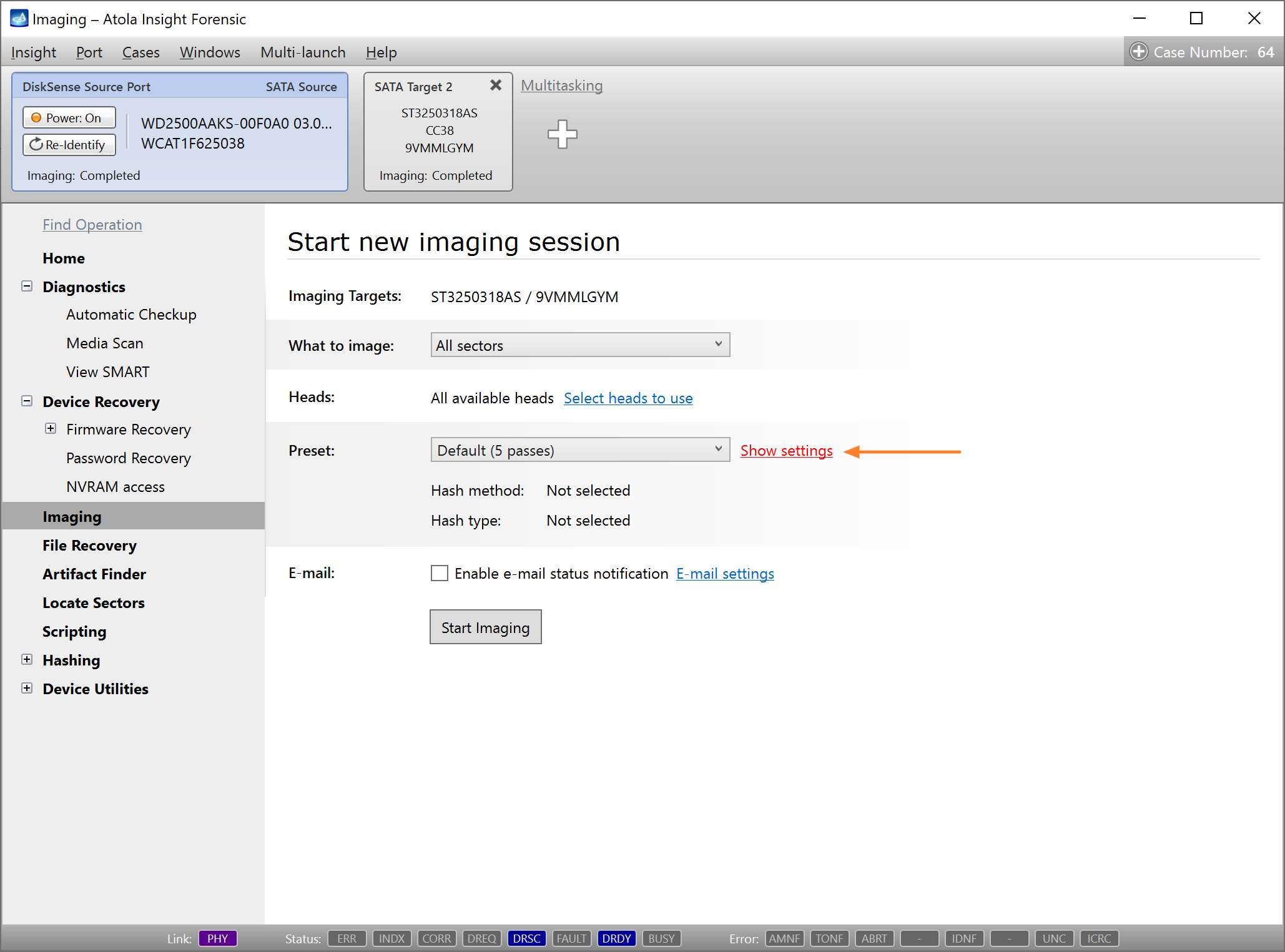
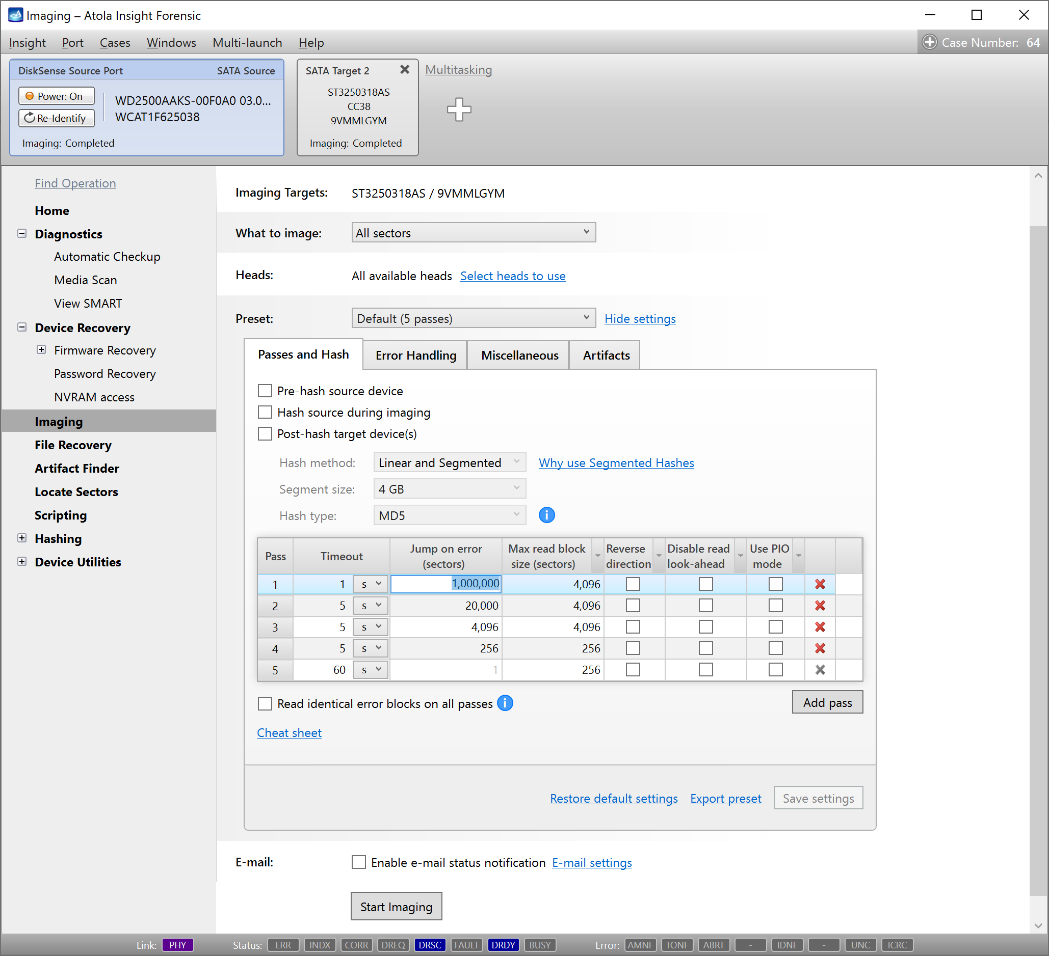
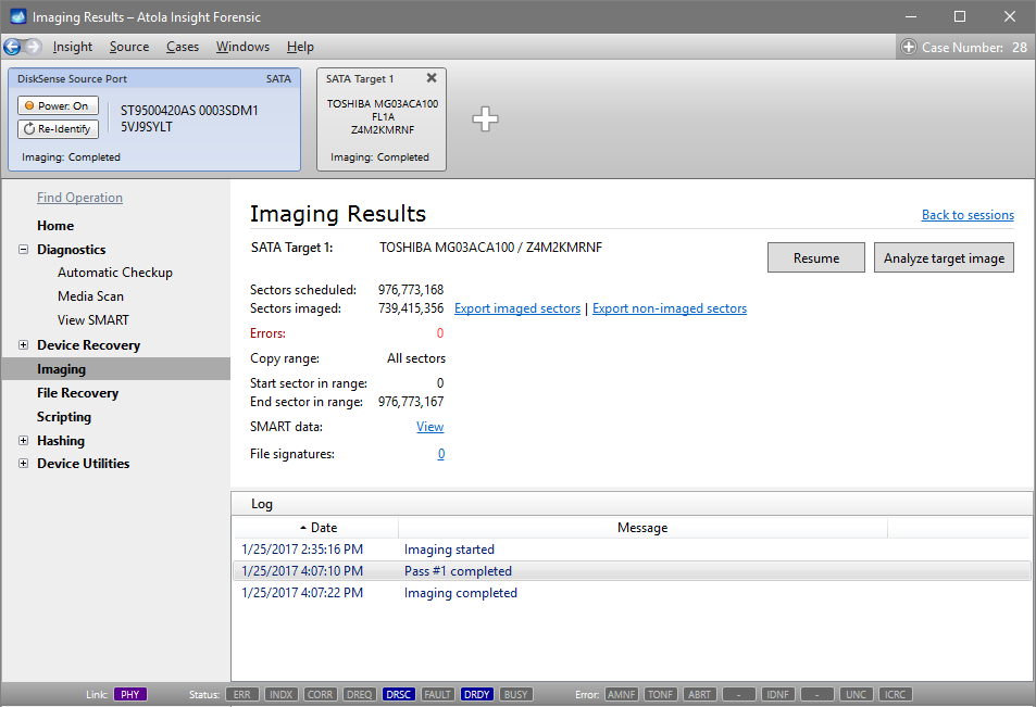
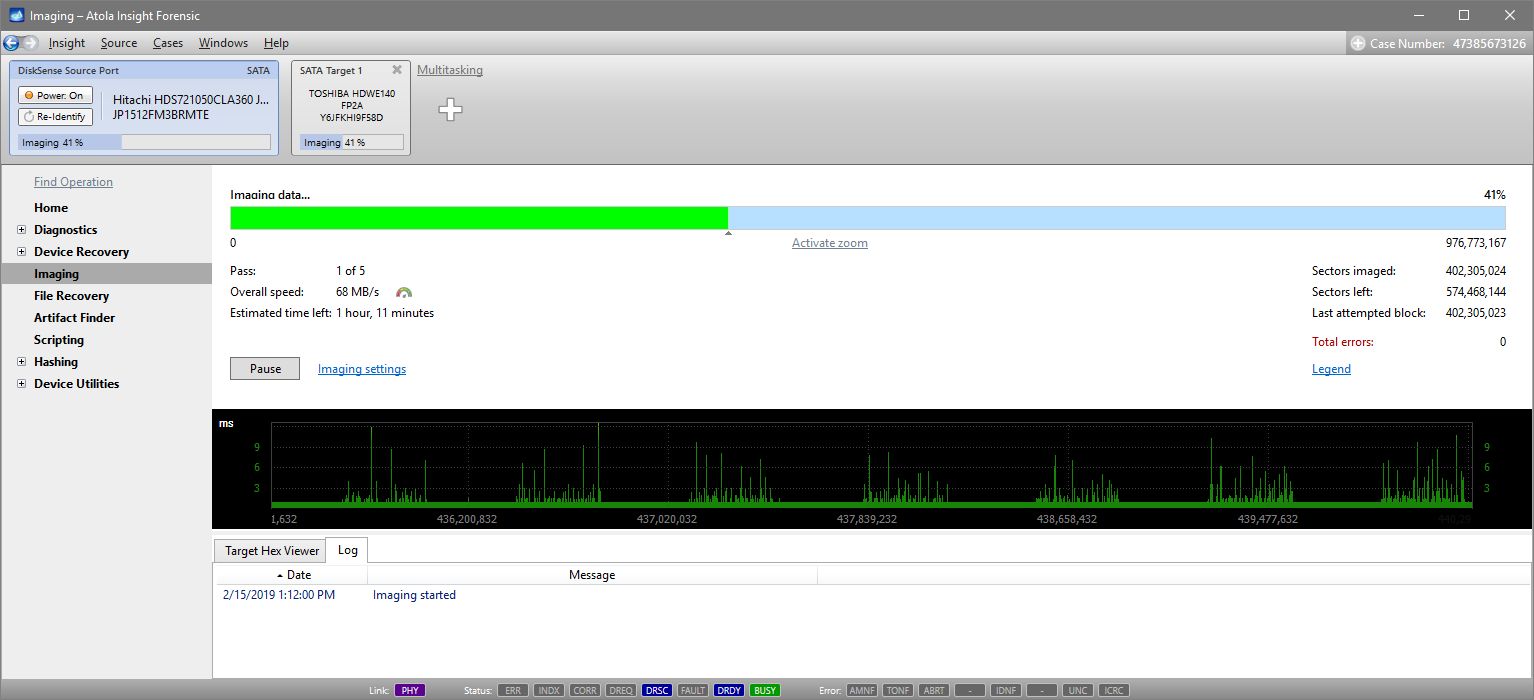
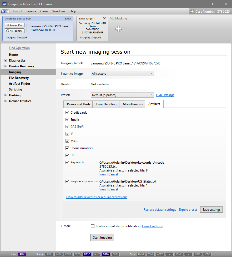
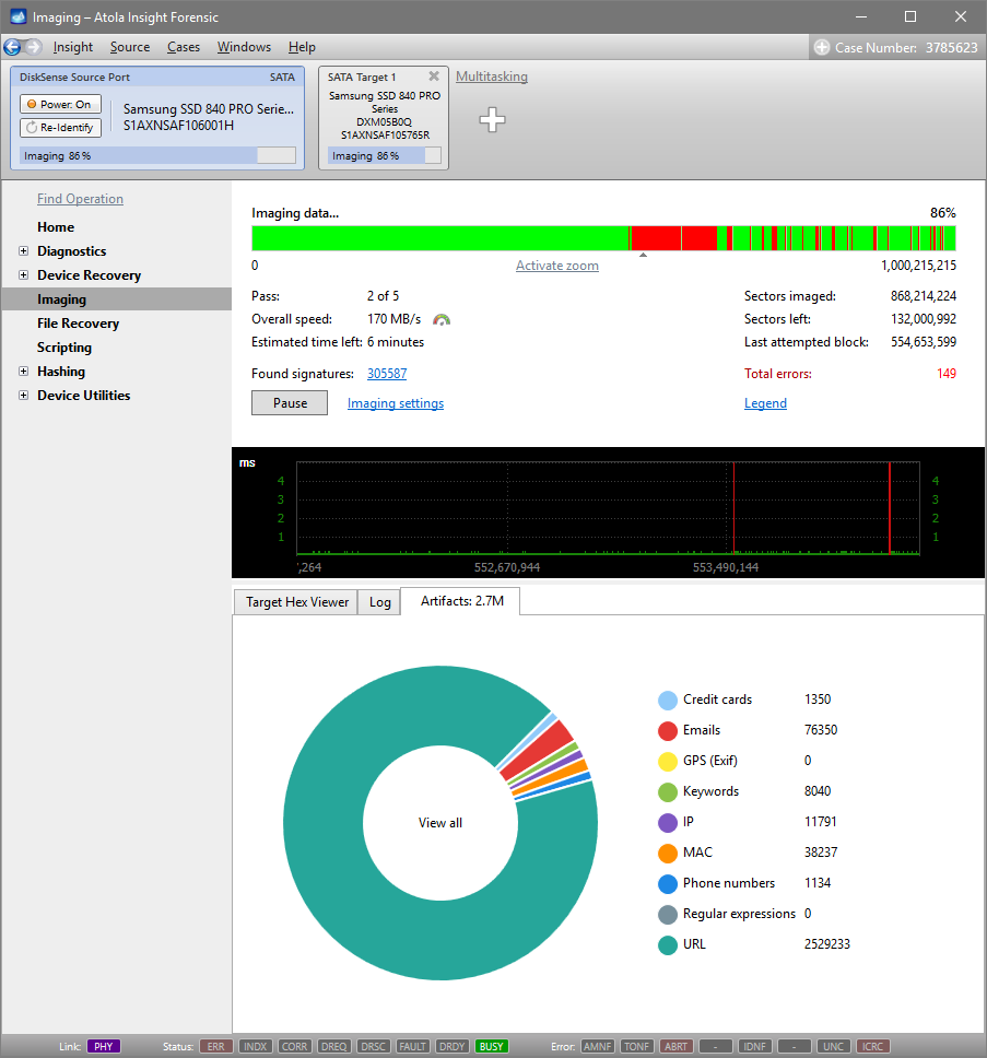
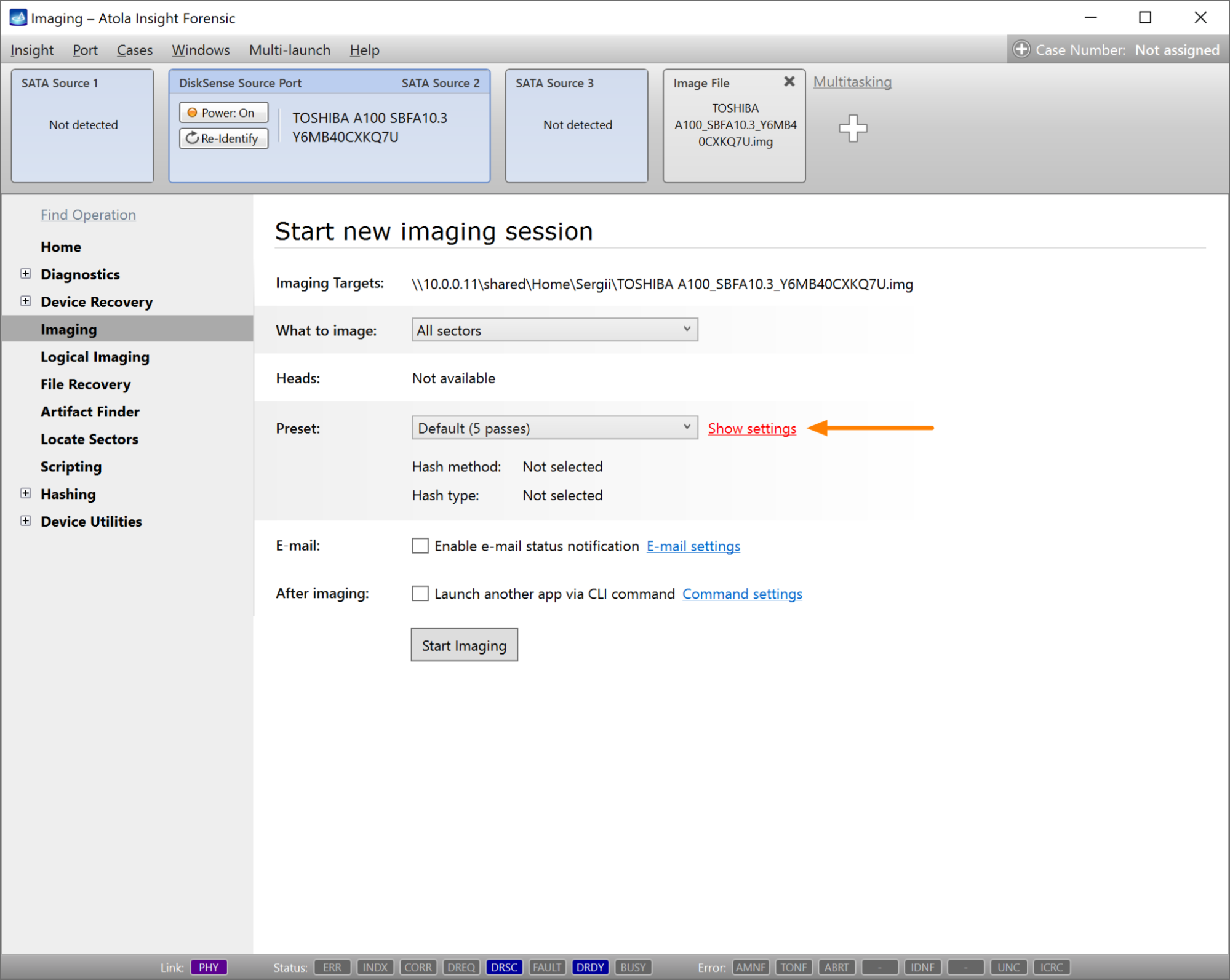
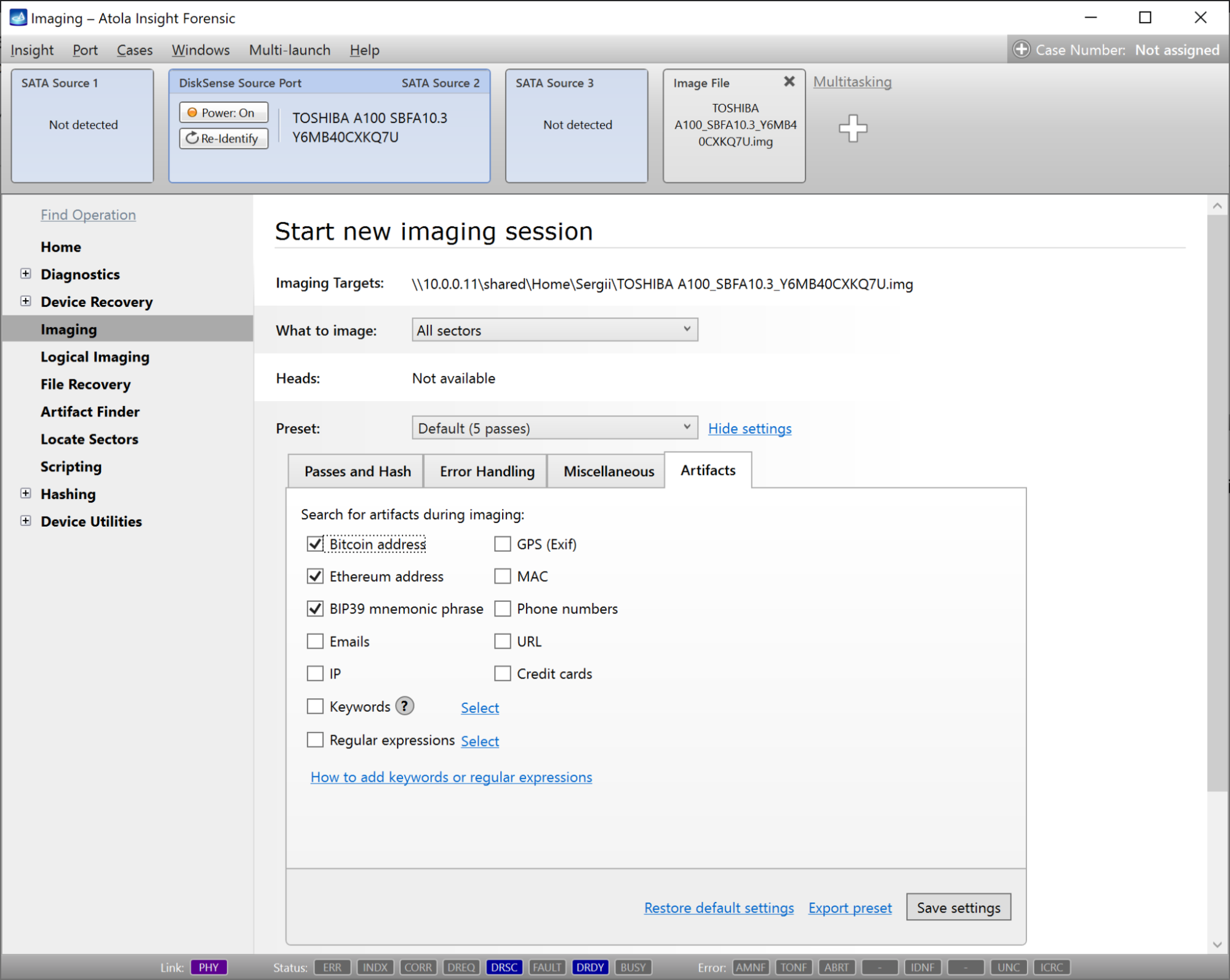
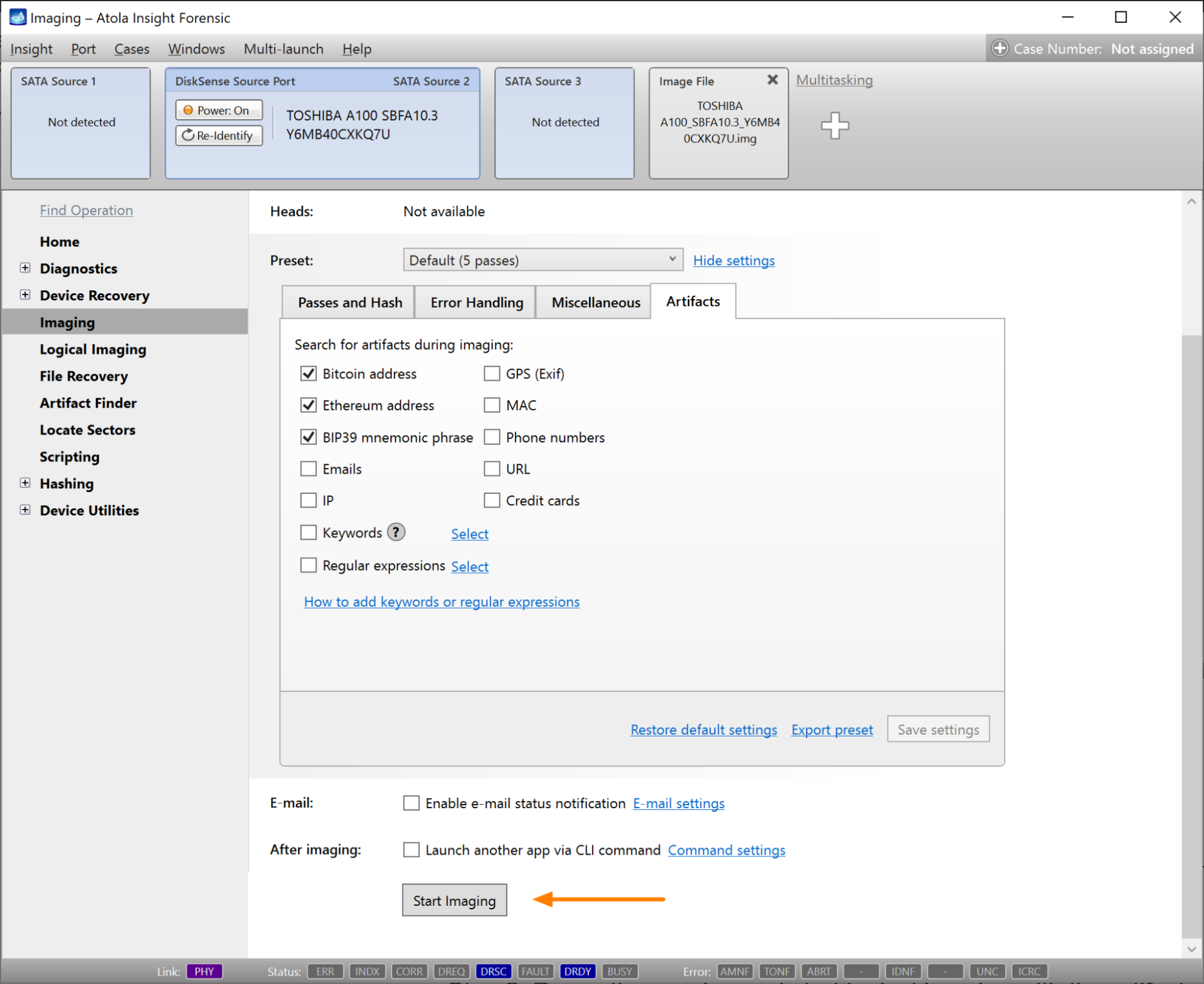
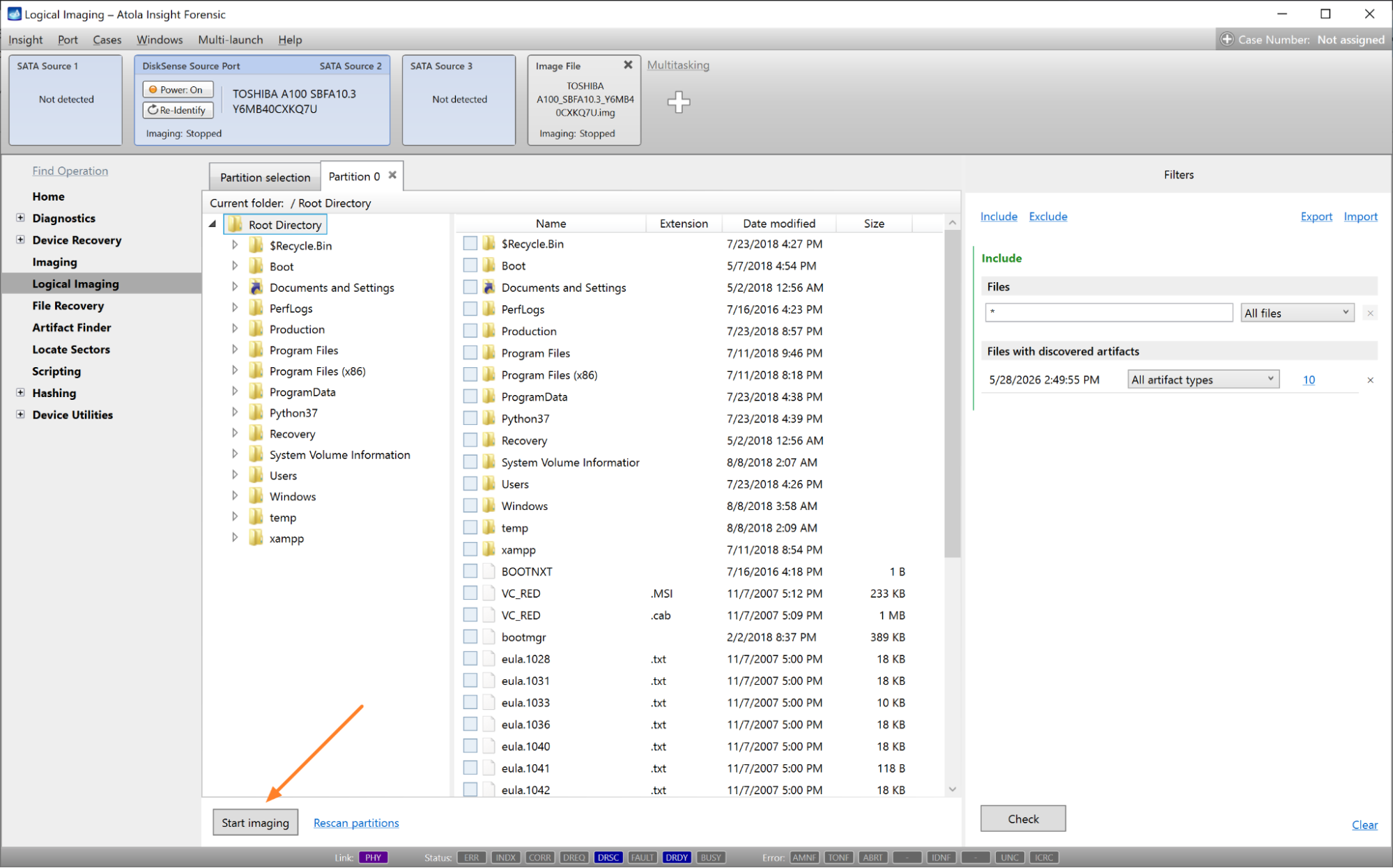
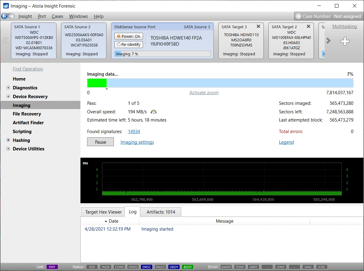
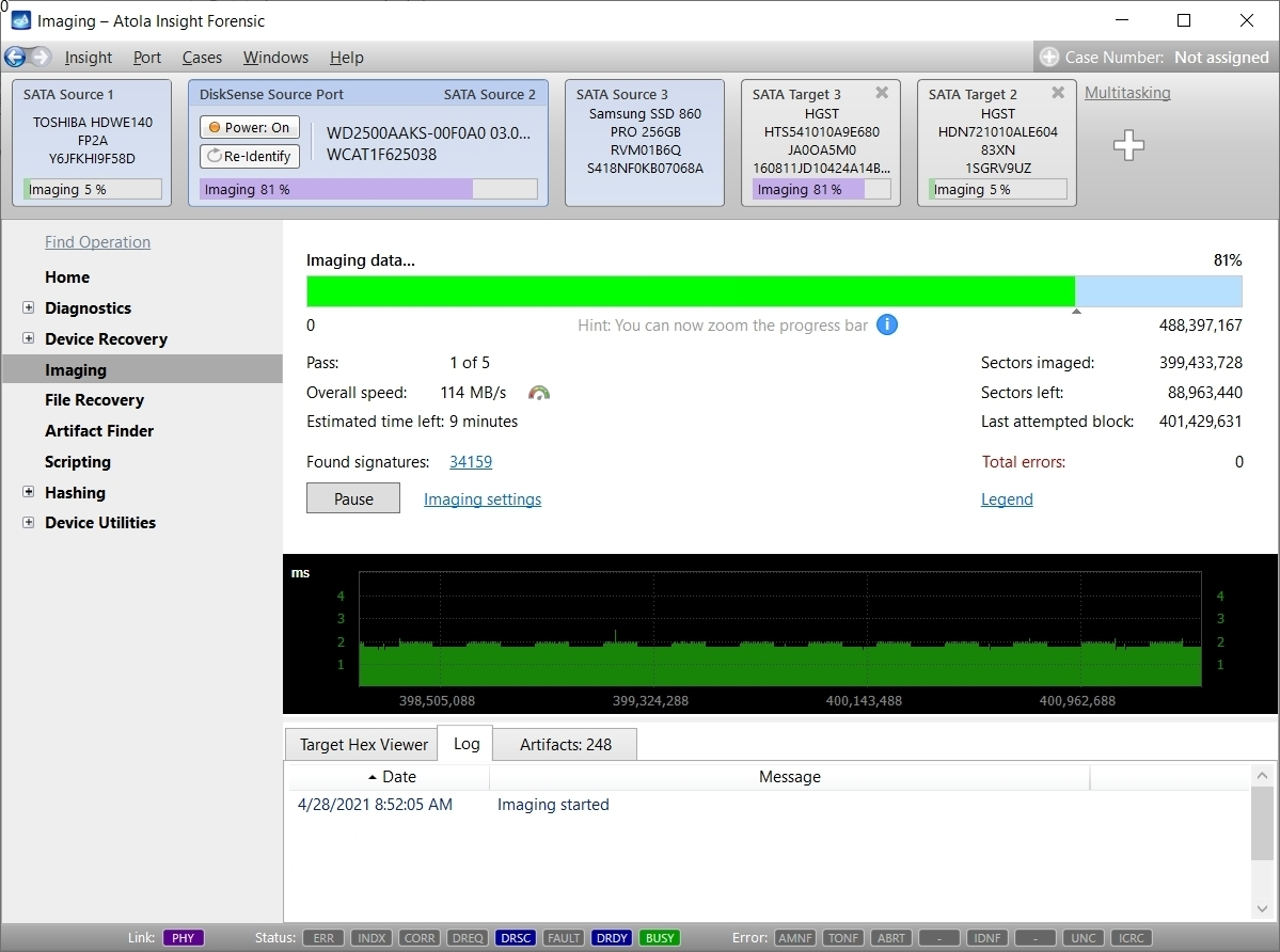
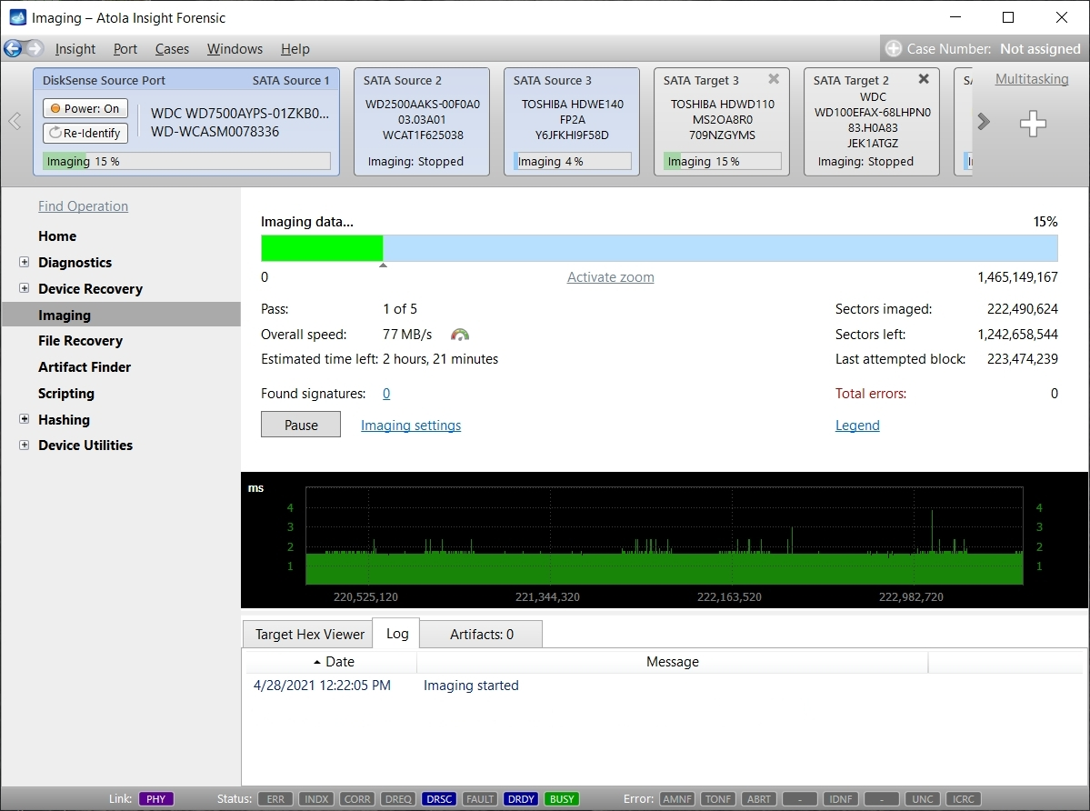
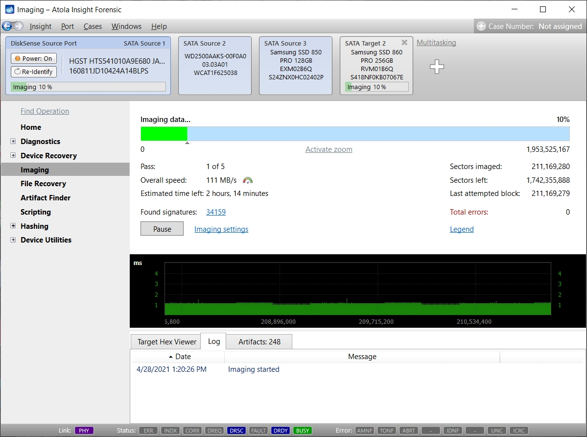
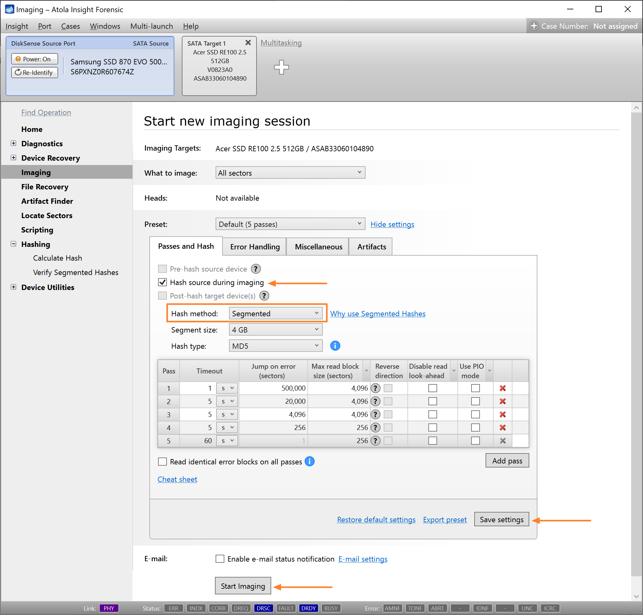
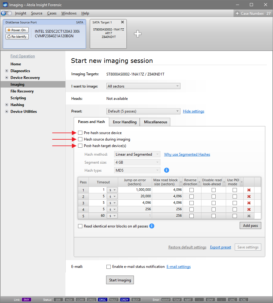
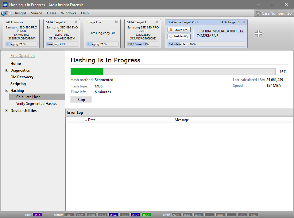
Step 5. Start imaging.
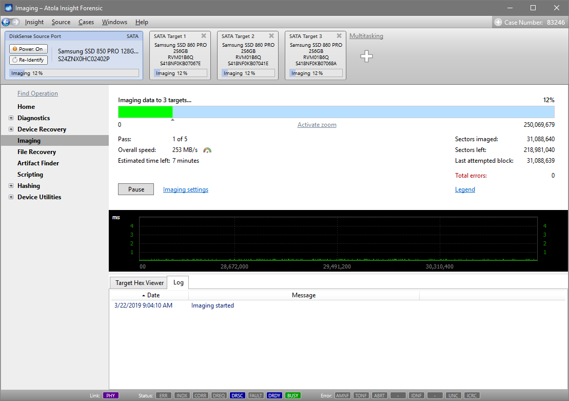
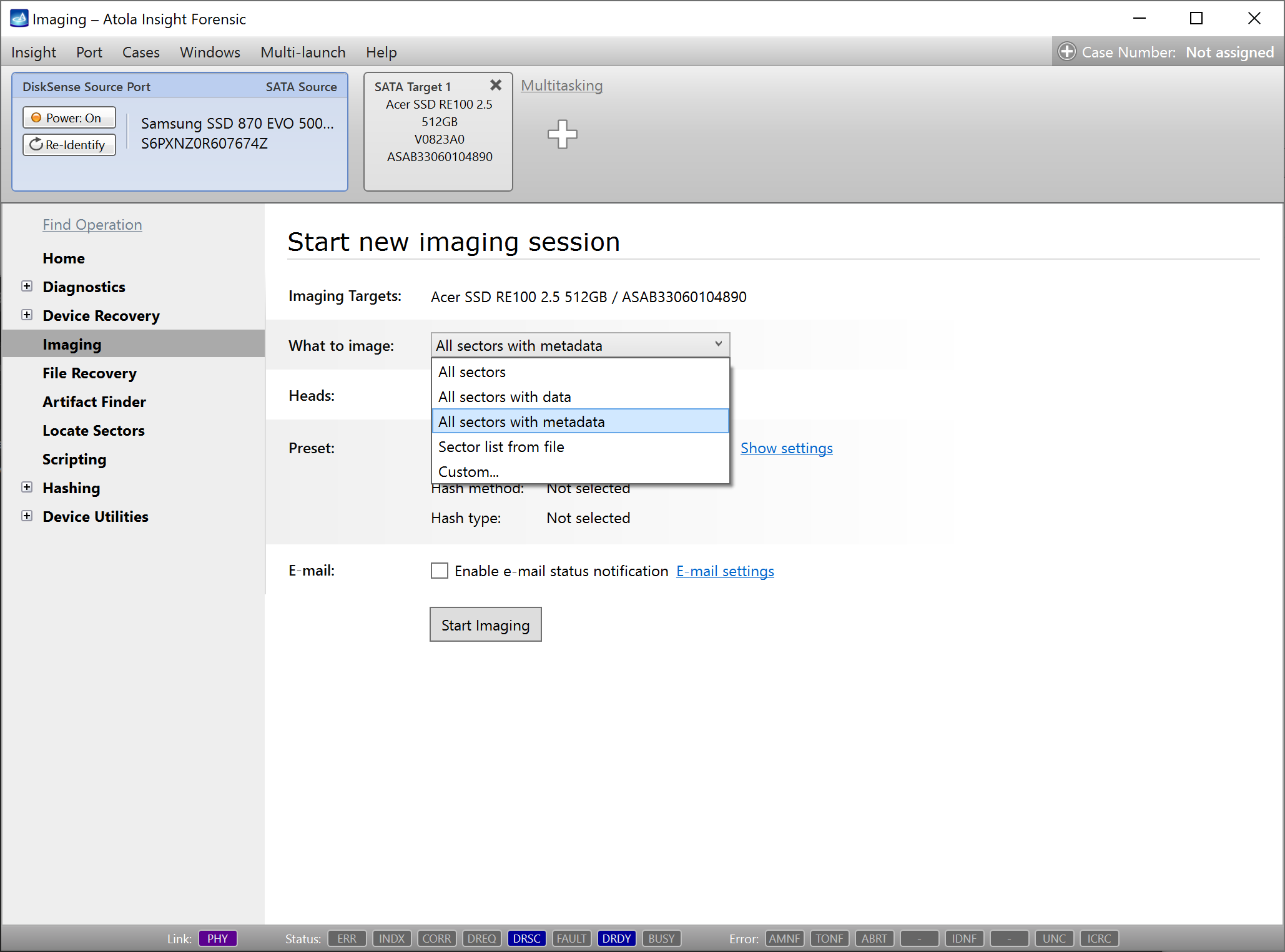
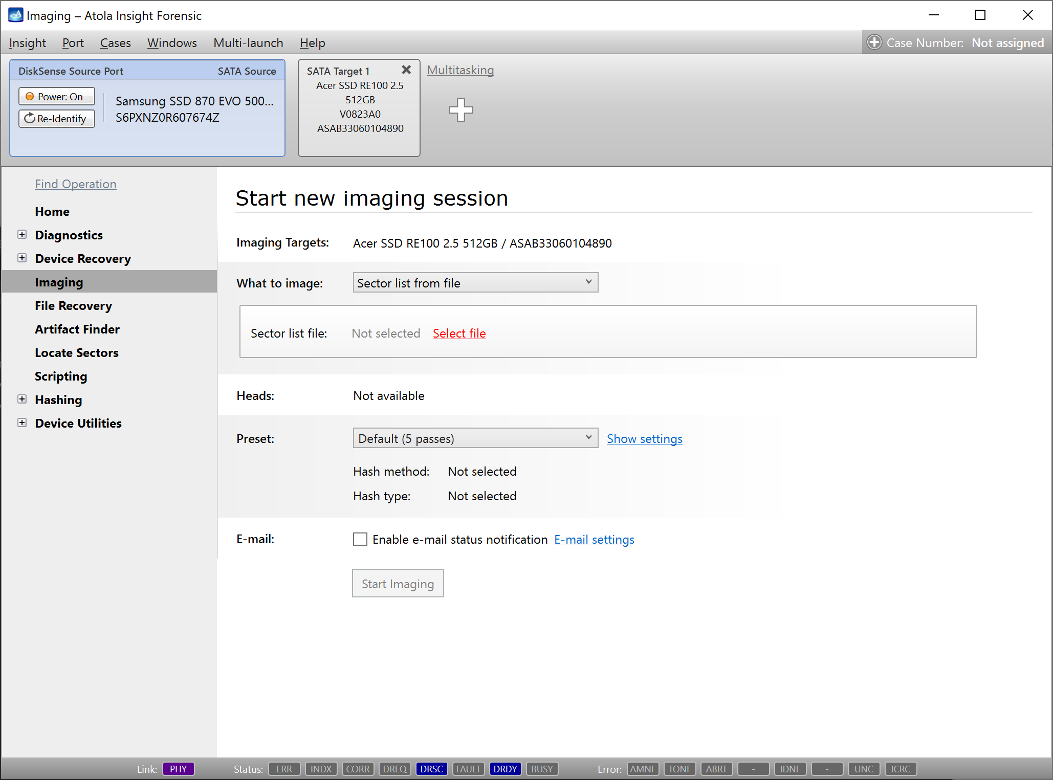
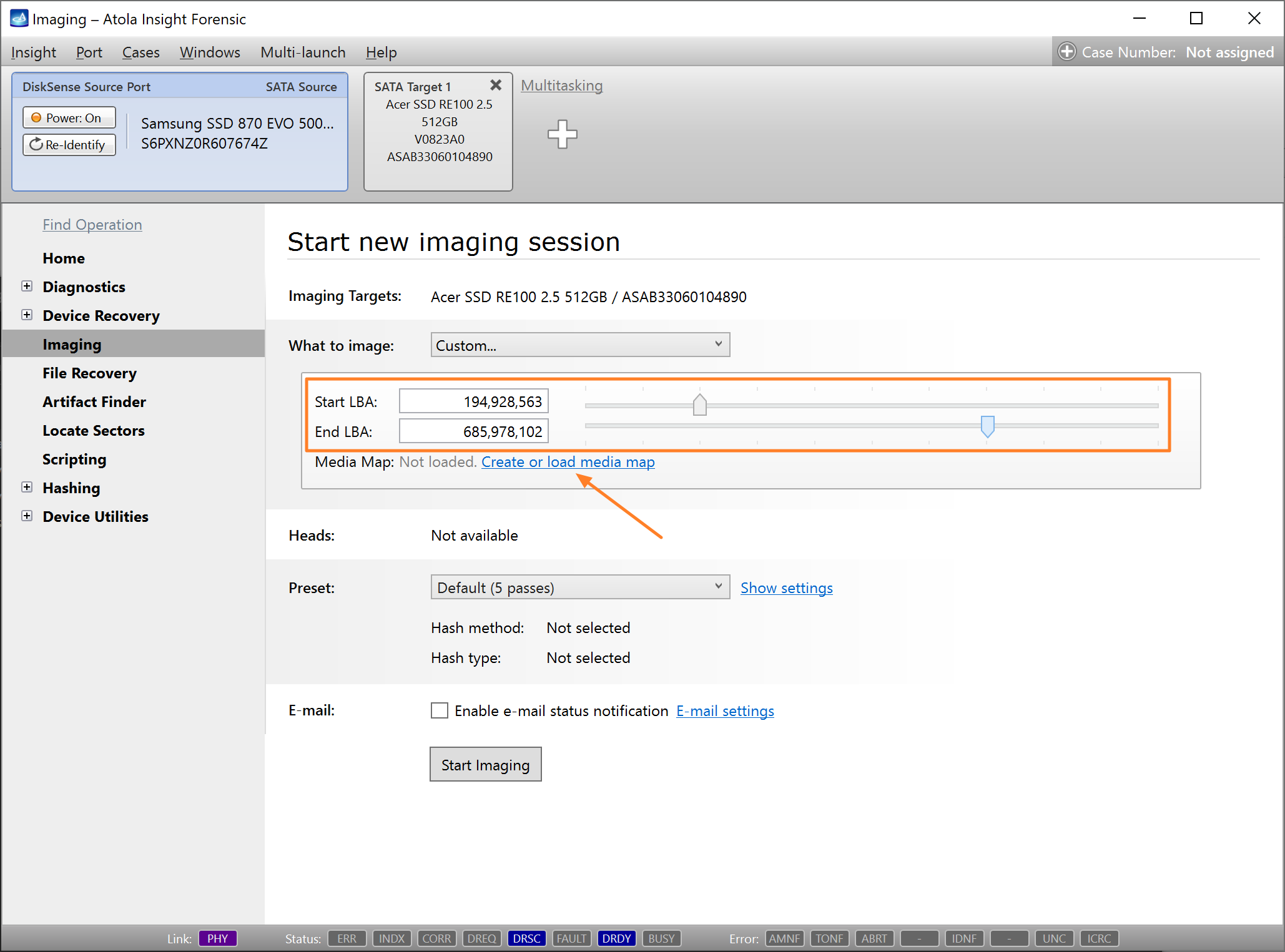
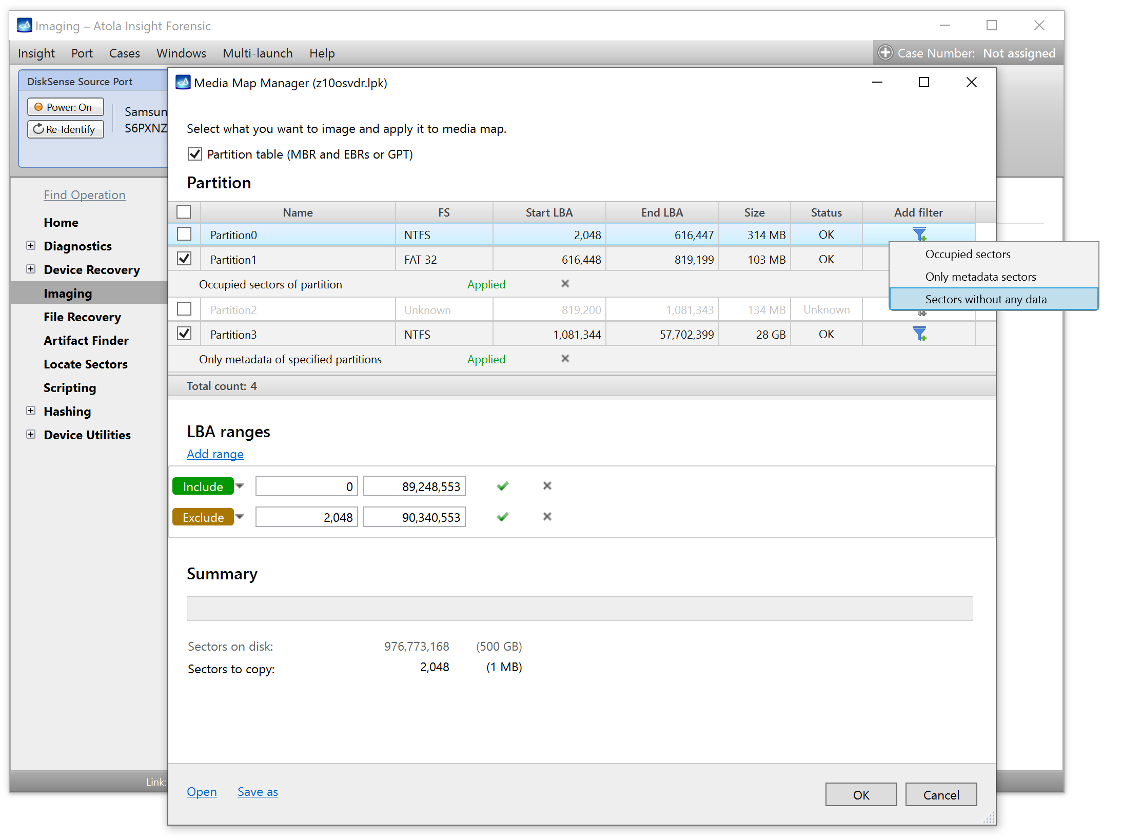
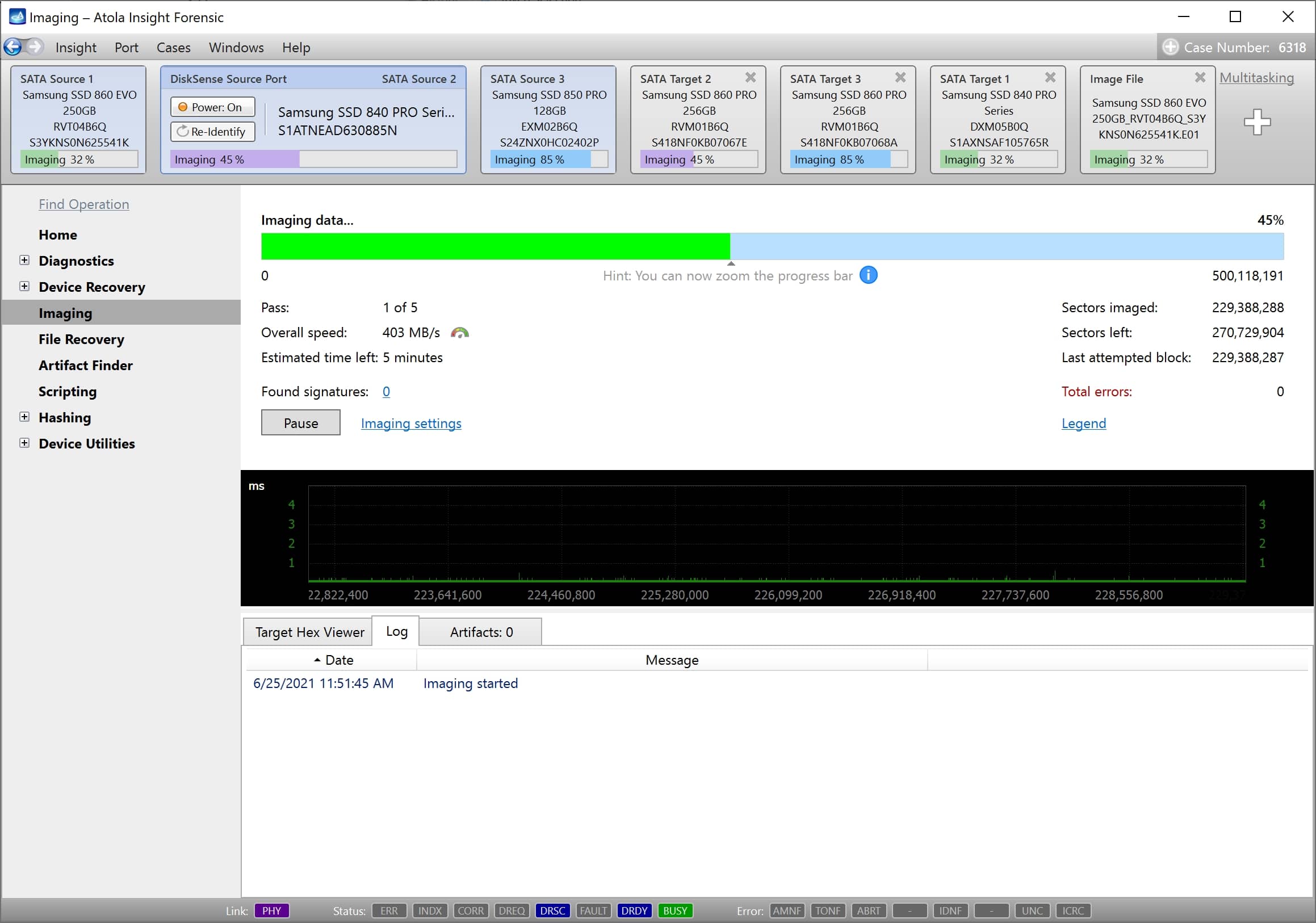
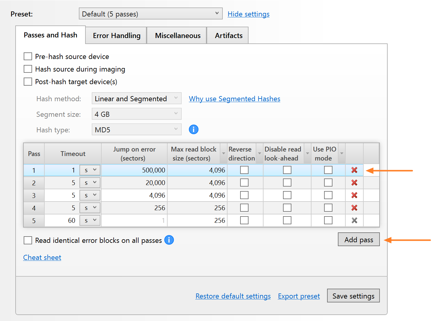
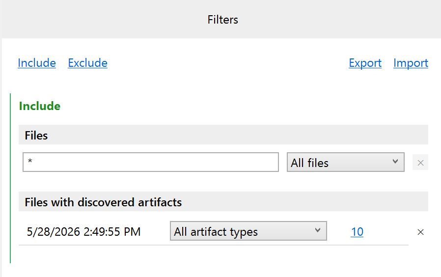
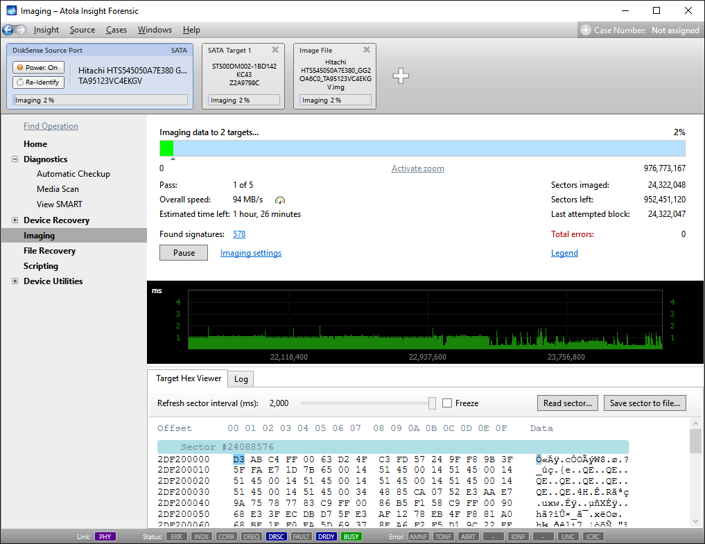
Imaging includes a wide variety of settings for tuning the process. Sometimes it is helpful when dealing with severely damaged evidence drives. However, the default imaging preset works great in most cases.
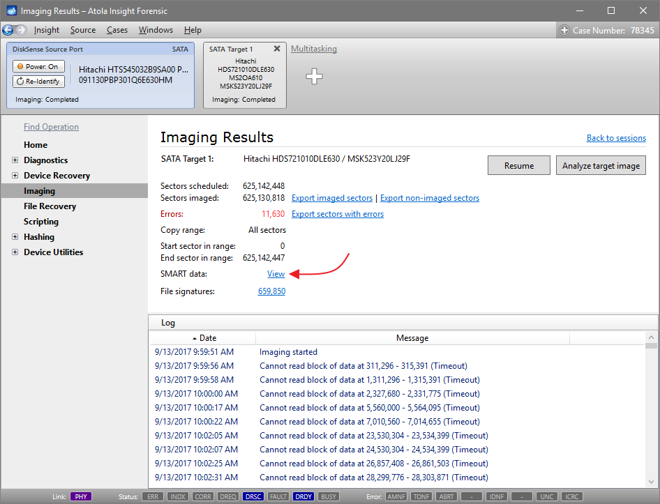
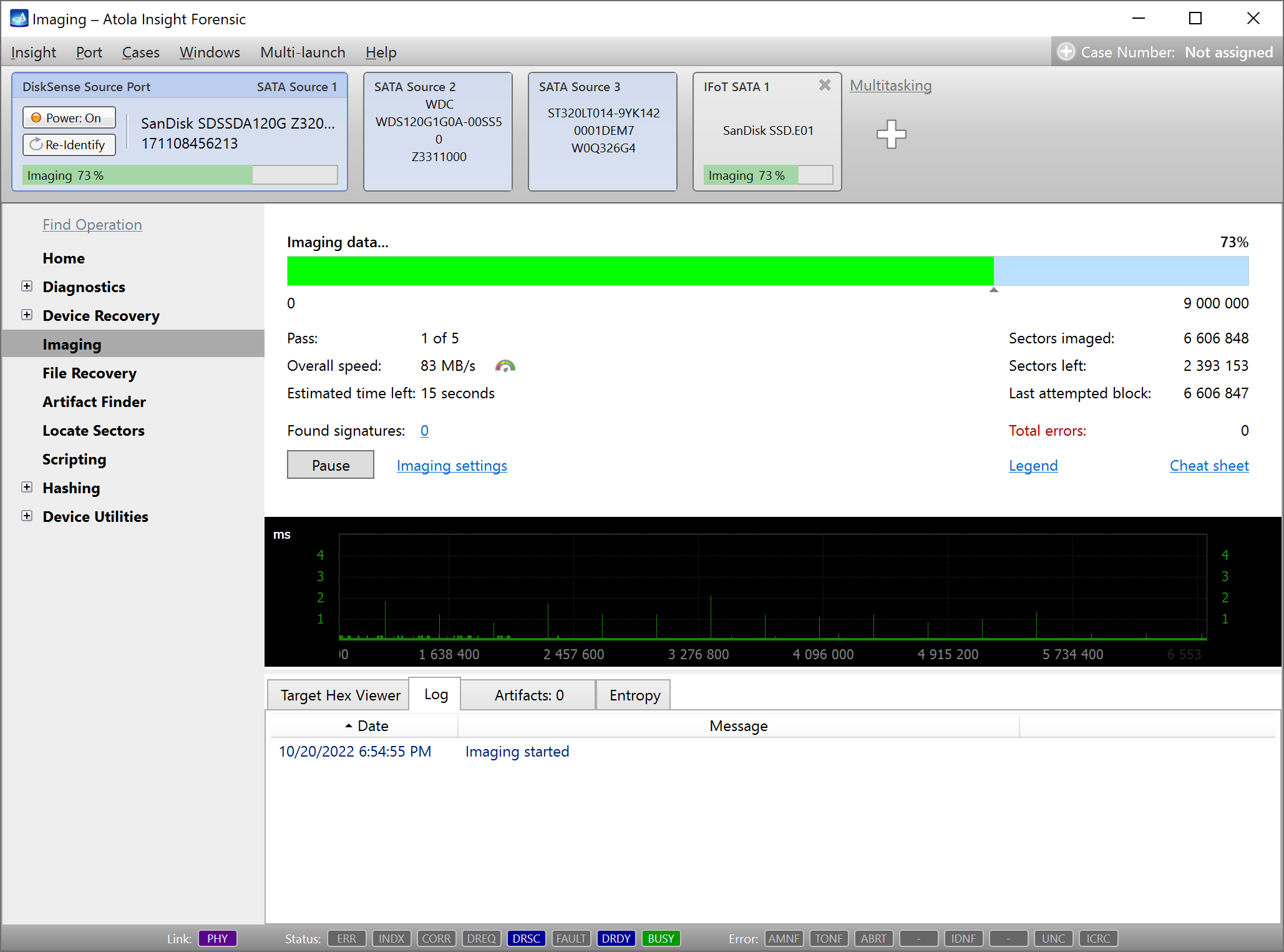
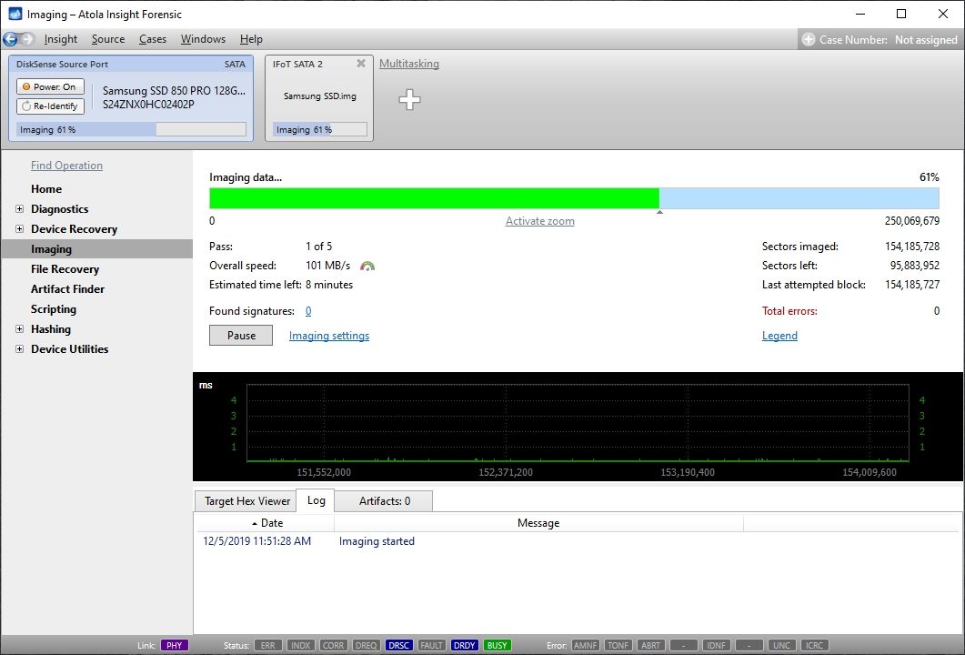
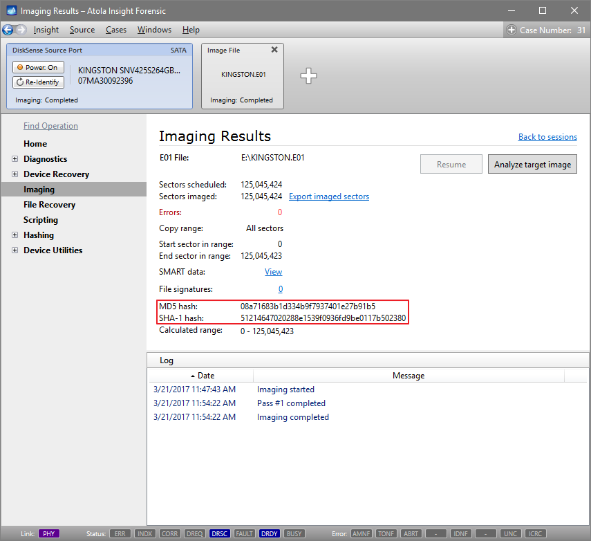
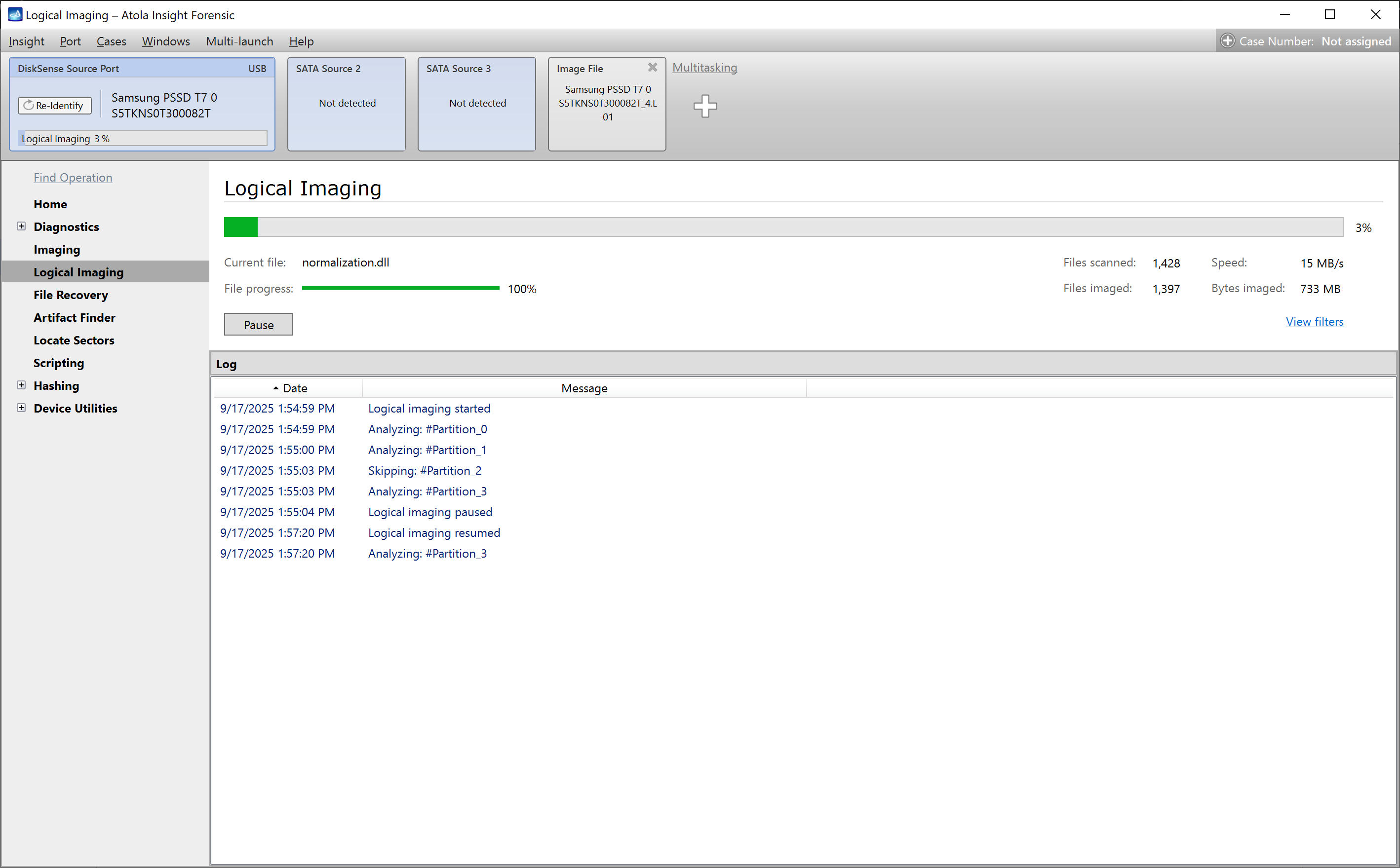
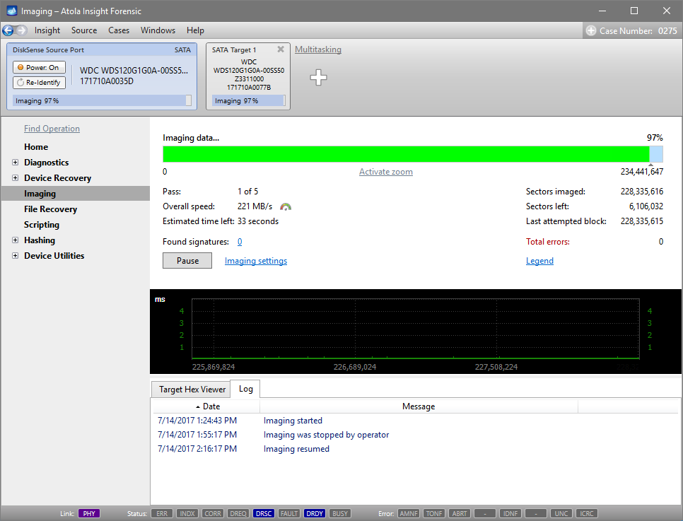
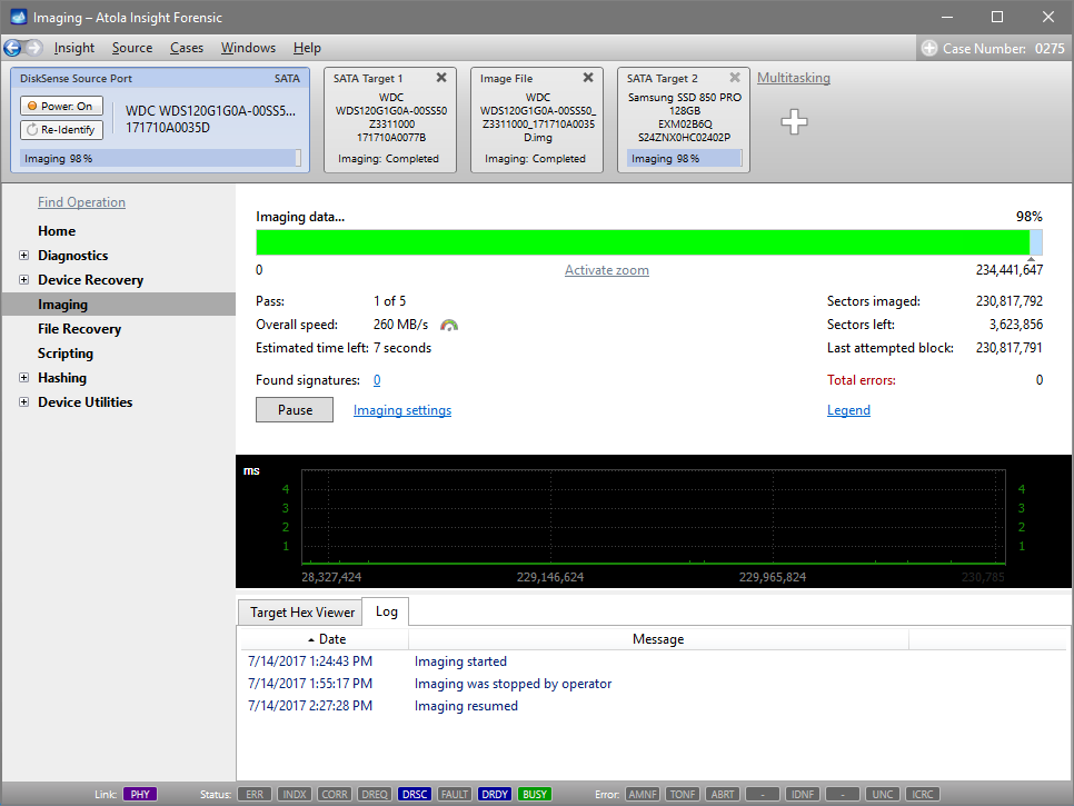
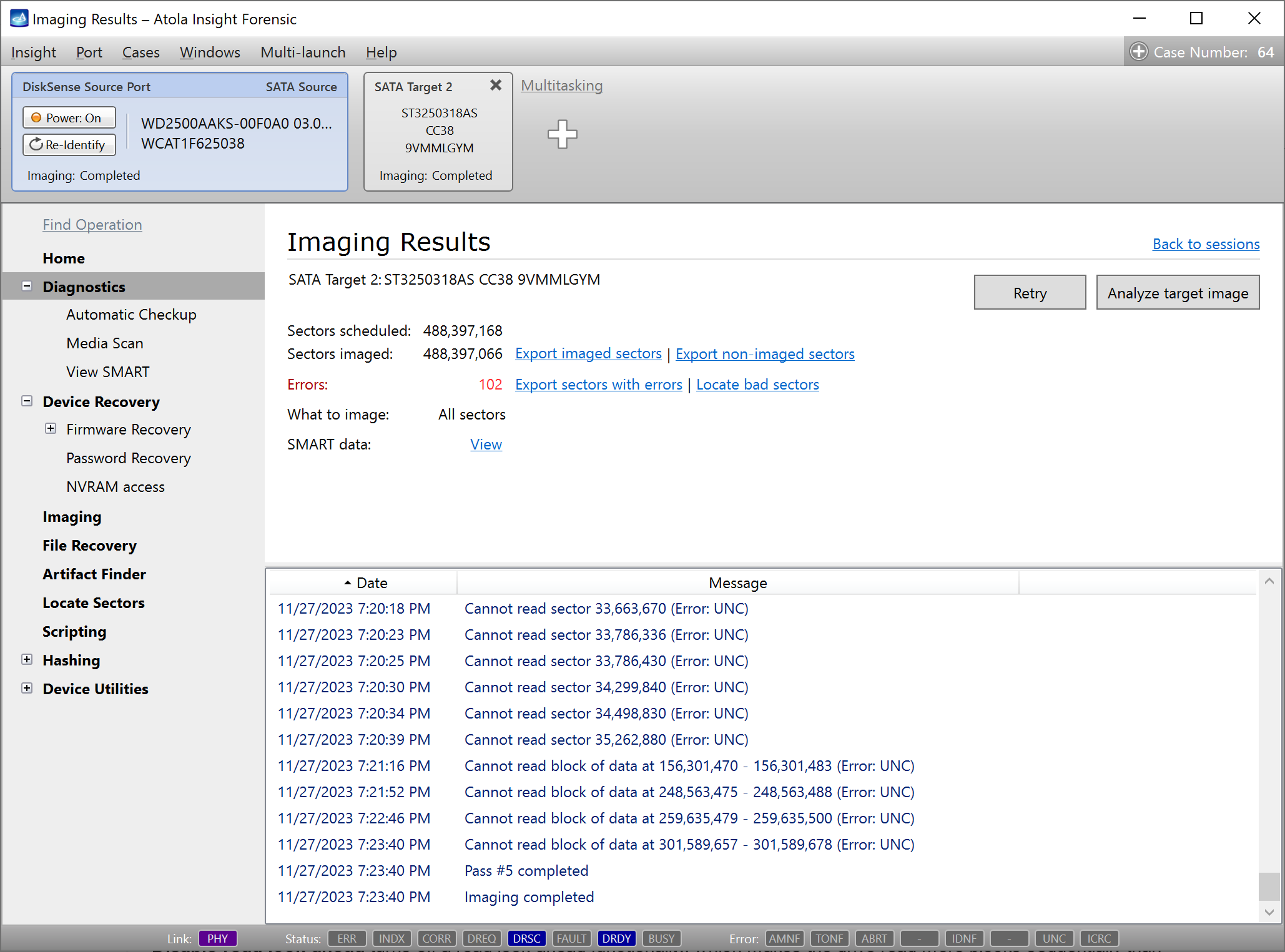
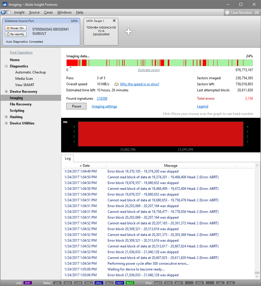
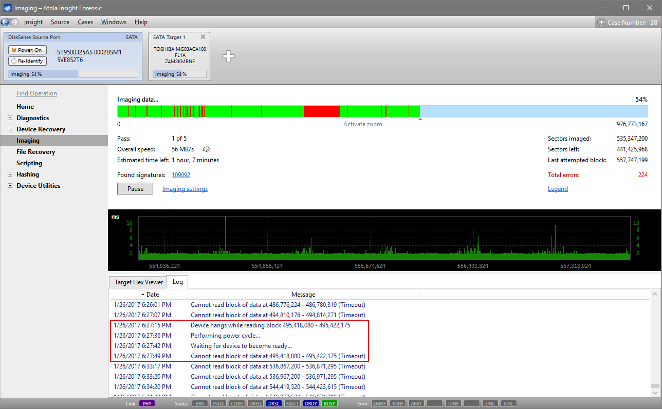
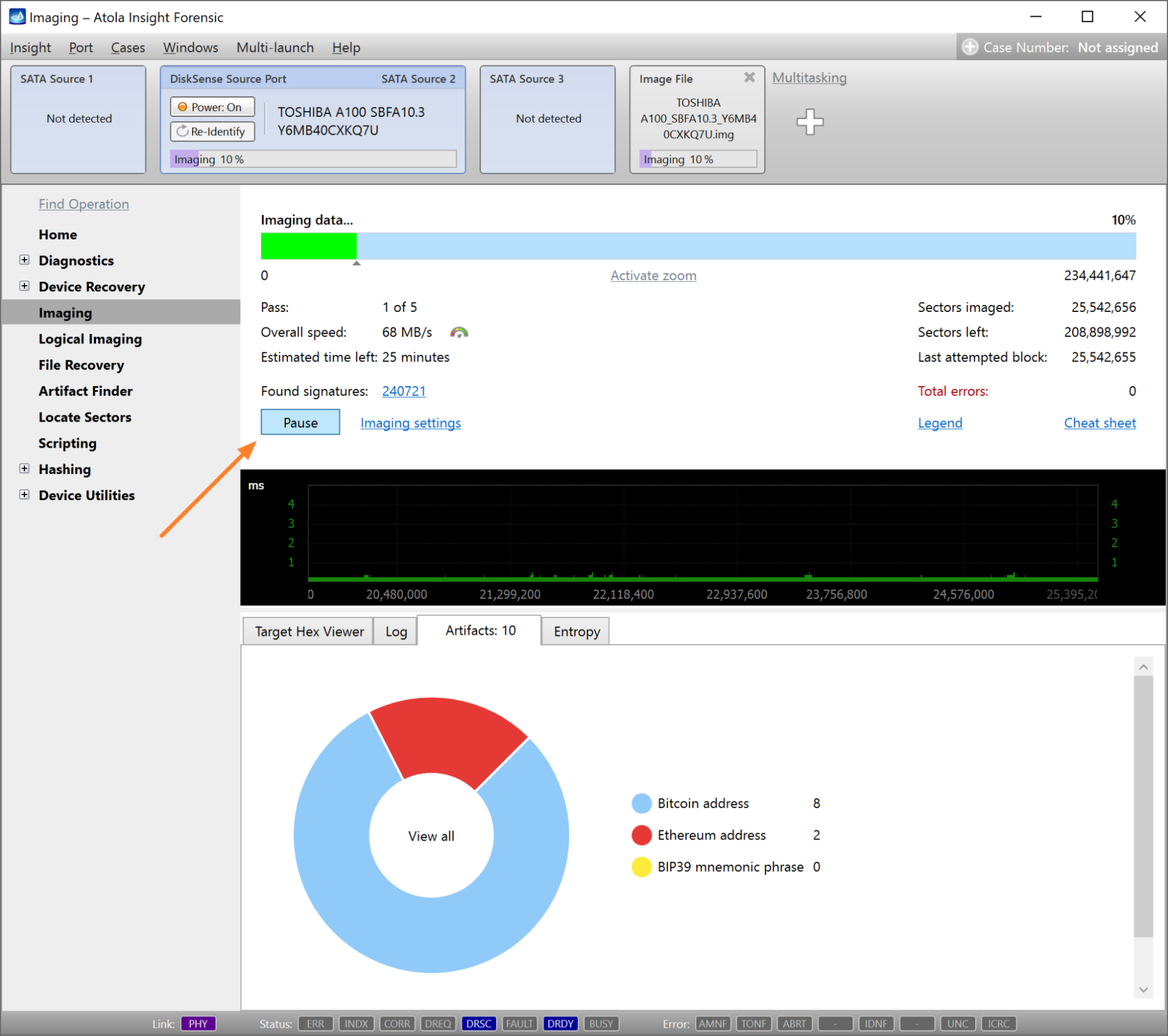
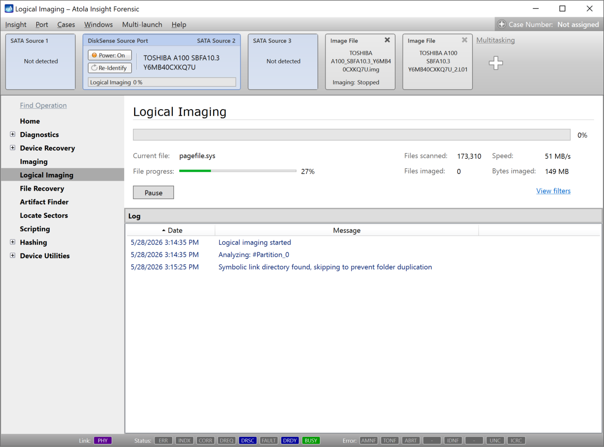
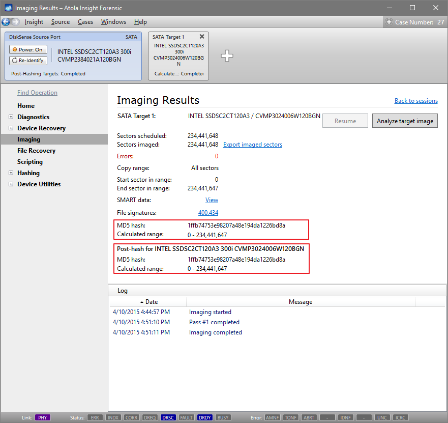
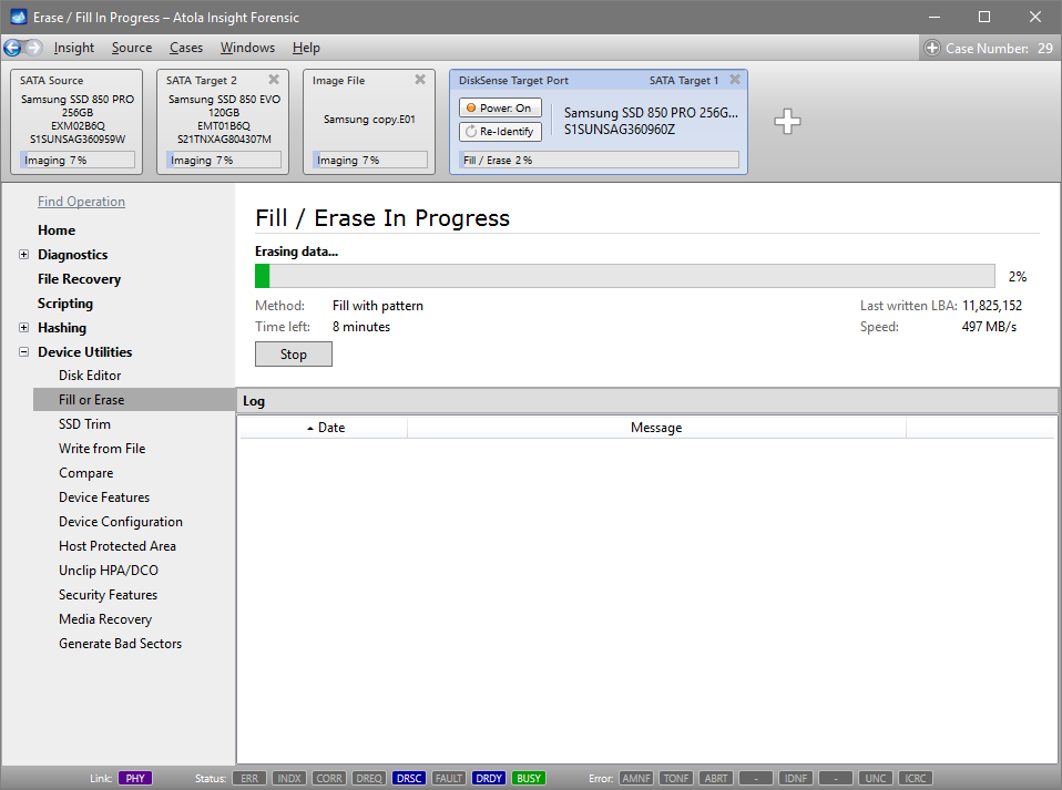
Here is just one button to click, Start Imaging, to get the imaging process running.
Bonus: Screencasts
Congratulations! You read the quickstart up to this section, and we have an award for you! :-) Here are a number of screencasts explaining specific features of Atola Insight Forensic.